
PSPi Zero Version 5 Assembly Guide – Updated November 15, 2021
Note regarding the new Raspberry Pi Zero 2 W:
The Zero 2 is compatible with my board, with the exception of the SD card slot. The pogo pins no longer line up, so the SD card must be inserted directly into the Pi Zero 2 W. The pogo pins are shifted far enough to where they won’t interfere with anything, so there is no need to de-solder them. Everything else works perfectly using the SD card image linked below in the software section. Be aware that there are now 2 different images. The original Pi Zero/Zero W requires the original image, and the Pi Zero 2 requires the Pi Zero 2 image. The Pi will not operate if you use the wrong image, but no damage will occur if you try the wrong image.
The feature description page is here
Purchase the board here
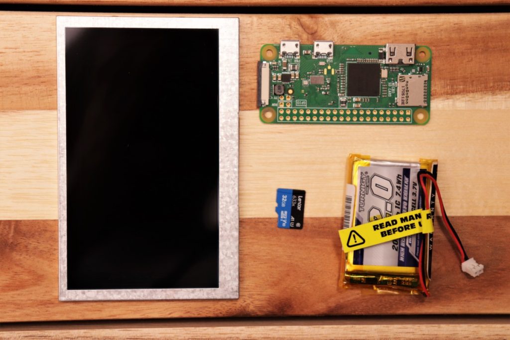
Here’s what you receive with your purchase:
PSPi Zero board
PSPi Headphone board
6-pin JST SH 1.0mm cable (with same-side pinout)
M2.5 screws
Raspberry Pi stacking header

To complete the build, you need the following:
4.3″ 800×480 LCD (available here) or 480×242 LCD from PSPi Version 4
Raspberry Pi Zero or Pi Zero W
Battery with JST PH 2.0mm connector (available here and here)
microSD card
USB to miniUSB adapter (available here)
PSP Charger (can be the original PSP charger, PSP USB charging cable, or miniUSB cable)
A mostly-complete PSP
Assembly Process
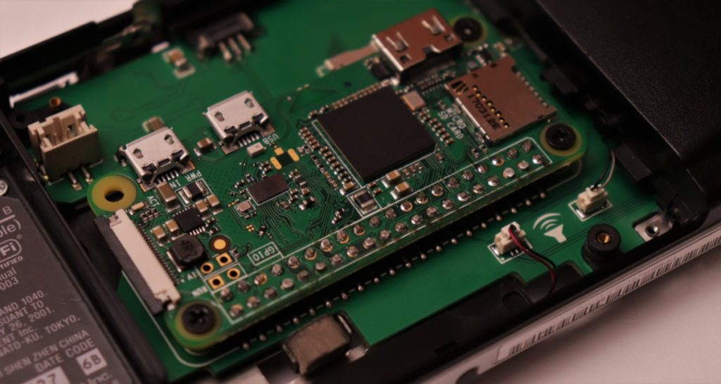
Mount the Raspberry Pi to the PSPi board, using the included three M2.5 screws


Insert the stacking header pins through the Raspberry Pi and into the female header

The pins from the stacking header should reach the bottom of the female header. Just make sure they don’t protrude through the board.

Solder the stacking header pins to the Raspberry Pi. Be careful when soldering, and make sure that solder and flux don’t drain down into the connector. If you are concerned that this may happen, then just solder a couple pins to lock things into place, then remove the Pi and stacking header from the PSPi board and solder the remaining pins.
Snip the excess from the stacking header pins using flush cutters

Remove the three screws, and remove the Raspberry Pi from the PSPi board.
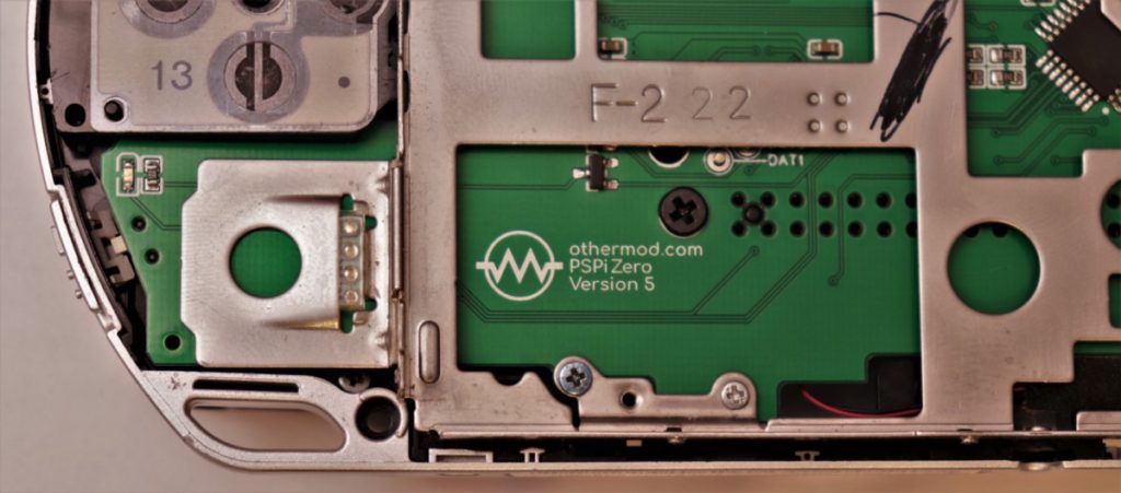
Install the headphone board into the PSP shell


Use 3 of the silver PSP screws to mount the headphone board and the small plastic cover


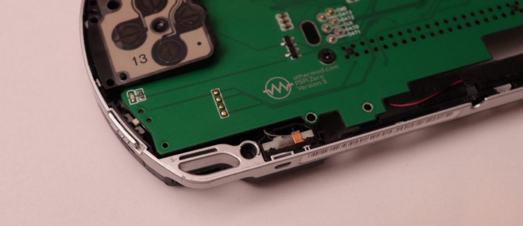
Plug one end of the 6-pin JST SH cable into the Headphone board, and the other end into the PSPi board

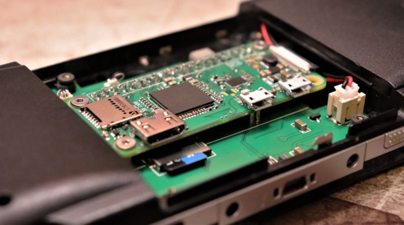
Install the PSPi board into the PSP shell. Excess wire from the JST cable can be pushed into the cutout on the Headphone board.


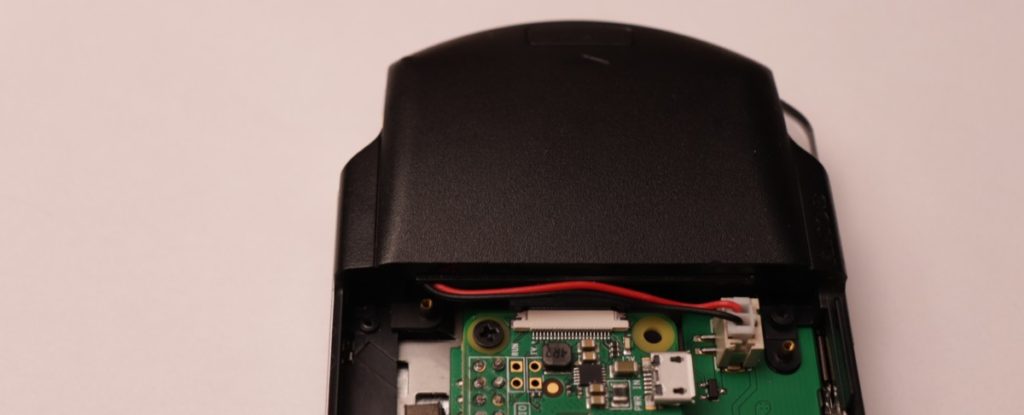
Insert the PSP charging cable into the charging connector
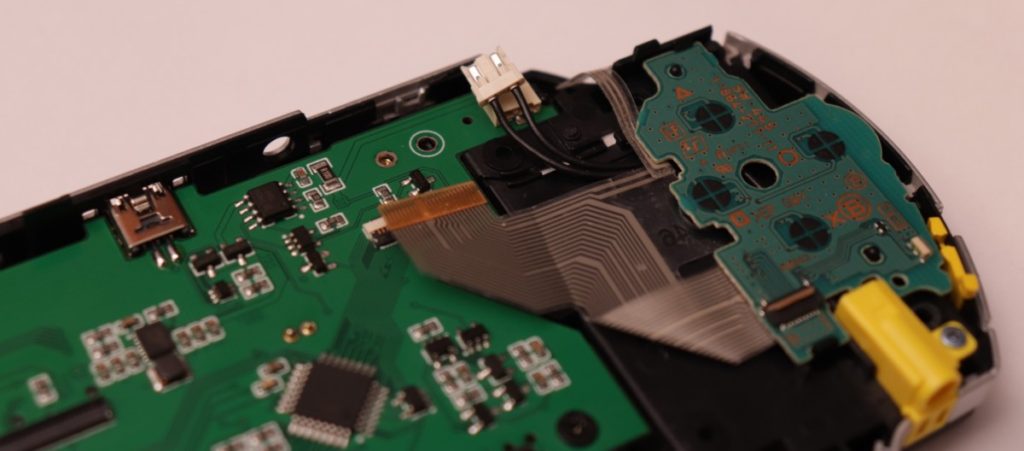

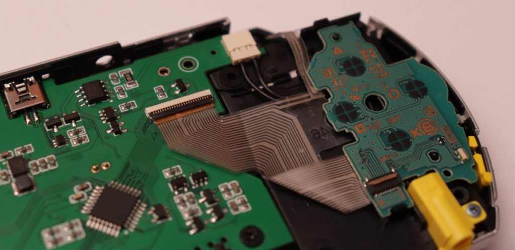
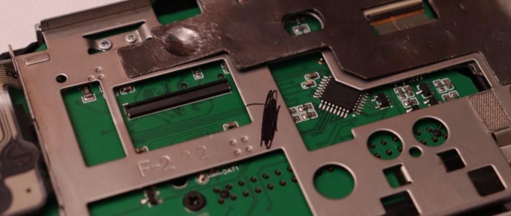
Insert the 10-pin and 24-pin FPC cables into the FPC connectors.
Be careful when locking the connectors closed. Apply an even force across the entire clip.


Route the speaker wires under the PSPi board. When routing the left one, keep it in the recessed area on the left. My speakers were temporarily removed so I could wash the case, so I’m reinstalling them now.
Pull the speaker wires through and install them into the connectors.

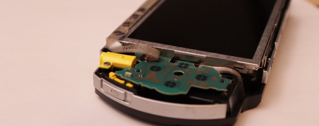
Install the LCD bracket, making sure to position the D-pad in the notch of the bracket.

Install screws in all the screw holes. Keep them all slightly loose initially, so the board is able to align as the remaining screws are installed.


Before fully tightening the screws, verify that the gold joystick pads are centered in the hole on the LCD bracket. Use the white perimeter around the pads to check alignment. It should self-align, but there is some wiggle room for manual alignment if needed. Once it’s aligned, tighten all the screws. Also verify that the rubber conductive pad is installed.
It is also very important that you check the back of the pogo pins on the USB and microSD, and verify that they are not touching the LCD bracket.
If they are, you can either bend that section of the LCD bracket upward and away from the pogo pins, or you can add some Kapton tape between the LCD bracket and the pins.
Install the two LCD bracket screws in the battery compartment

Install the Pi Zero back into the PSPi board. Reinstall the three screws.
Install the LCD.
Be careful when locking the connector closed. Apply an even force across the entire clip.


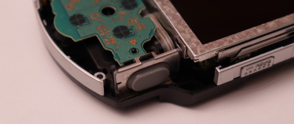
Install the extra button bracket


Put a screw in the D-pad
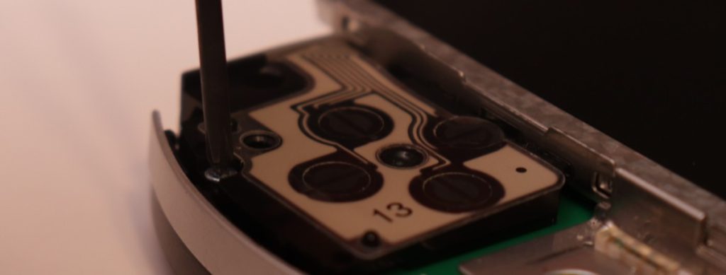
If not already done, install the rubber contact pad and retainer for the right trigger
Install the left and right trigger buttons


Install the faceplate. Install the four black screws and one fine-pitch silver screw.


Install the battery

Install the microSD card

Install the cover

Software
Option 1 – Installation Instructions Using Image
Download the ready-to-use images here:
Image for the original Pi Zero/Zero W from Google Drive or Torrent
Image for the new Raspberry Pi Zero 2 W Google Drive or Torrent
Extract the image and use imaging software (such as Win32DiskImager, Etcher, or Raspberry Pi Imager) to image your SD card
Option 2 – Manual Offline Installation Instructions
This is written for an offline installation. It assumes that you have a freshly imaged microSD card with RetroPie 4.7.1
Start by visiting the othermod Github at https://github.com/othermod/PSPi-Zero-Version-5
Download everything by clicking the “Code” button and hitting “Download ZIP”

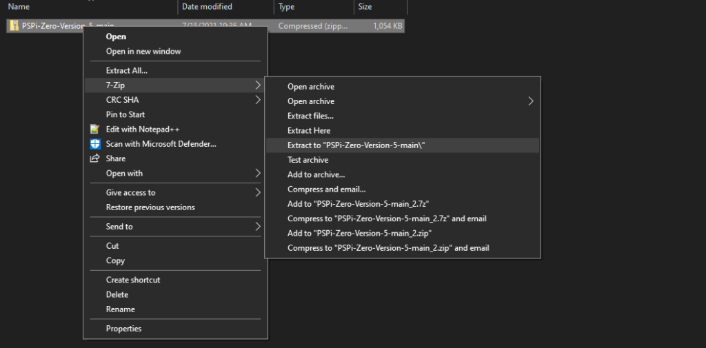
Once you do that, extract the download using your favorite ZIP file extraction software. I use 7zip.
Open the extracted folder, then copy the PSPi folder and the file called config.txt to your microSD card.


Allow it to overwrite the files on the SD card.

Install your SD card into the microSD slot on the PSPi board
Attach a USB keyboard (using the miniUSB connector on the PSPi board) and power the system on by pushing the power switch upward for a moment.
Once the system boots, press F4 on the keyboard to exit to the command line.
Type the following command and press Enter to install everything:
sudo bash /boot/PSPi/setup.sh
It will install everything, then it will automatically reboot. The configuration is finished after the reboot, and the PSPi is ready to use.
Hi,
sadly, the torrent for the Zero V2 Image seems to be broken. Tried it with Transmission on Linux and LibreTorrent on Android, but nothing get’s Downloaded.
I’m uploading it to google drive now. I’ll post a link in a bit.
https://drive.google.com/file/d/1L-83DOw1nLsuN6U6shBkFoucKfzP67q1/view?usp=sharing
I have tried the zero 2 image but sadly I get no sound. Is there a way to debug/check that everything is ok?
Make sure the switch on the left side (what used to be the PSP WiFi switch) is in the up position.
Do you get any error messages in the command prompt when you load a game?
Yes that fixed it. I was always wondering what that was used for 🙂 Stability is great btw
Hi. I’m pondering getting one of these. I have also built a Freeplay Zero and a Piboy DMG.
Do I have to use the stacking header? Can I use a Pi Zero that already has a header? Do you know if the Pimoroni hammer header fits?
You have to use the stacking header or something very similar because of the height limitations. The normal soldered header is soldered in the wrong direction, and the plastic retainer makes it too tall. The hammer header has the same issue because of the plastic retainer.
does the fie for the pi zero w 2 come with roms? and if not. do you have any suggestions on were to get those?
It does not. I’ll can only refer to the first paragraph of this page https://retropie.org.uk/docs/Transferring-Roms/
Hi,
Do you have an updated link to the Google Drive for Pi Zero 2W image? The one on this page does not work. Thanks!