
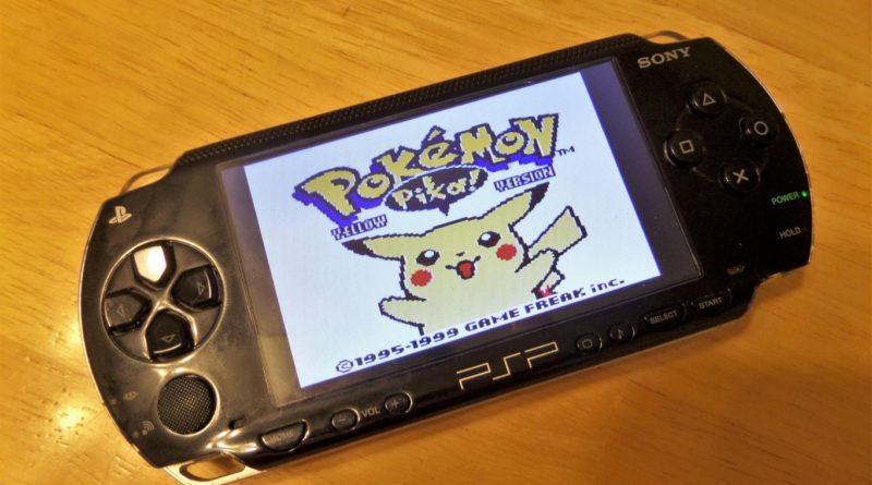
PSPi 1000 Version 2
This project is now complete. I’ve posted a video below of PSPi 1000 Version 2 in action. Please continue to ask questions in the forum. I’m happy to answer them.
If you’re looking for something much, much easier to build, check out Version 4.
Welcome to the PSPi 1000 Version 2 build page. Another dead PSP is being given a second chance using the $5 Pi Zero. The main goal with this project is to spend as little as possible on the components. When possible, I will create instead of purchase, and I’m making tutorials along the way that should be helpful for any Pi project. This one will have all the same features as PSPi 1000 Version 1 and even a few more. I’m documenting every part of it with photos, and if anyone wants more information on any part of it I’m happy to respond to questions.
For those making your own version of the PSPi or a similar project, head over here to the PSPi Forum and create a topic if you have questions or need help.
For those that want to build your own, here are the components used in the build.
IRF7319 Dual Mosfet on eBay or Amazon
LM393 Voltage Comparator on eBay or Amazon
Lithium Charge Controller and Power Board on eBay or Banggood or otherMod.com
4.3″ Composite LCD on eBay or Amazon or otherMod.com
24-Pin FPC Connector on eBay or Amazon
24-Pin FPC Cables on eBay or Amazon
10-Pin FPC Connector on eBay or Amazon
10-Pin FPC Cables on eBay
Lithium Batteries on eBay or Amazon or otherMod.com
Audio Amplifier on eBay or Amazon or otherMod.com
BAT54C Dual Diode on eBay or Amazon
26 AWG Wire 6-Color Set on Amazon
USB Charging Cable on Amazon or eBay
MiniUSB to USB Adapter on eBay or otherMod.com
Mini USB Female Connector on otherMod.com
8GB MicroSD Class 10 SD Card with Adapter on Amazon
Pi Zero Kit with Class 10 8GB MicroSD and Power Supply on Adafruit
Miscellaneous Resistors and Capacitors
Features and Details:
4.3″ 480×272 Composite LCD
Completely gutted, and only the original button boards are used
GPIO audio output with Class D stereo amplifier
Working miniUSB port on top
The Sony Memory Card slot converted to microSD and wired to the Pi Zero
Original power jack is used to charge
Momentary press of power button turns the console on and off. Pushing the button when the Pi is on shuts the OS down and powers the system off.
Controls wired directly to GPIO pins
2 cell phone batteries in parallel for extended play time
Low battery warning LED and charging LEDs
A few things I’ve customized:
Power On/Off Circuit in Emulation Software
PSP and Pi Zero Pinouts
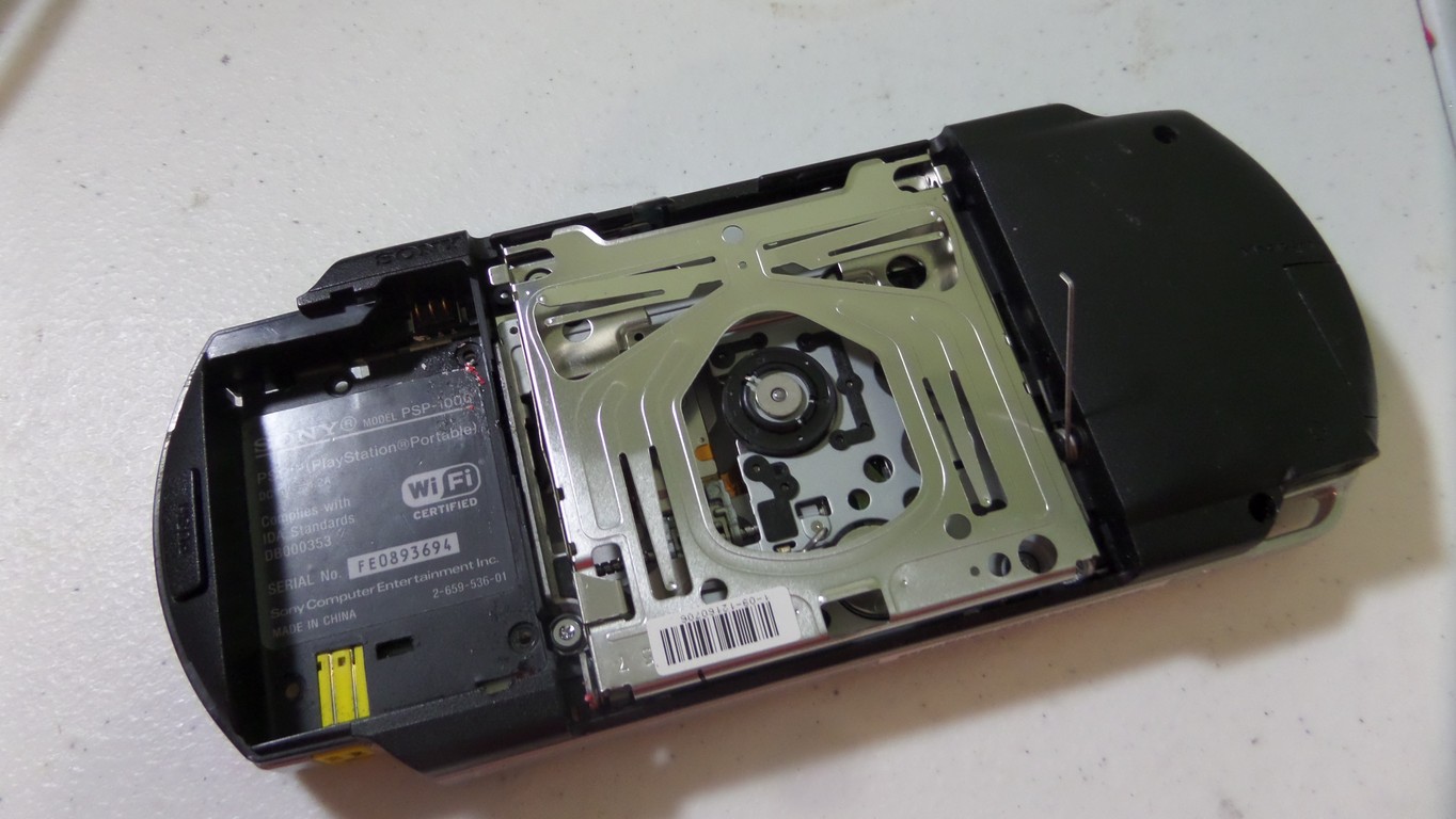
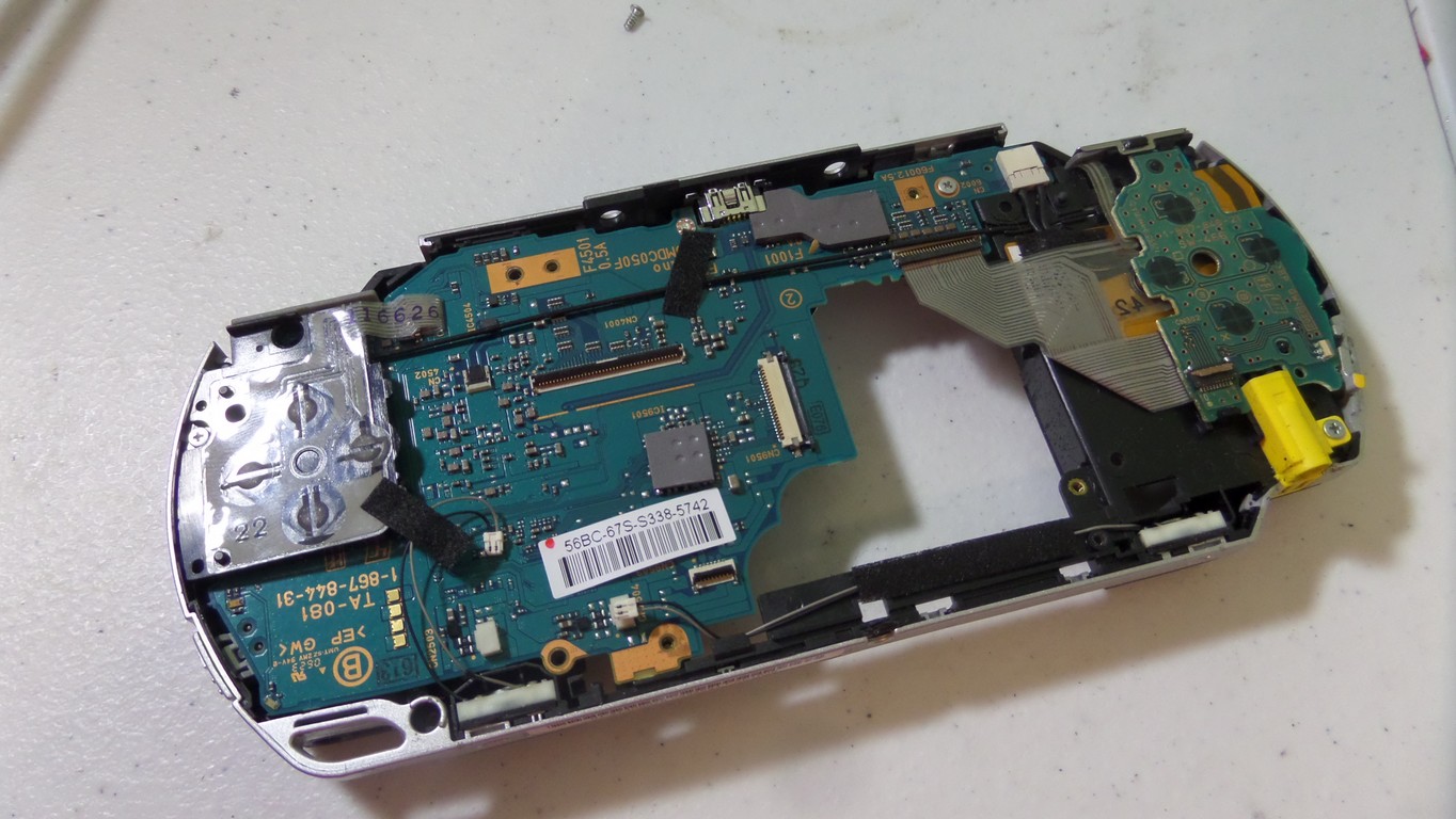
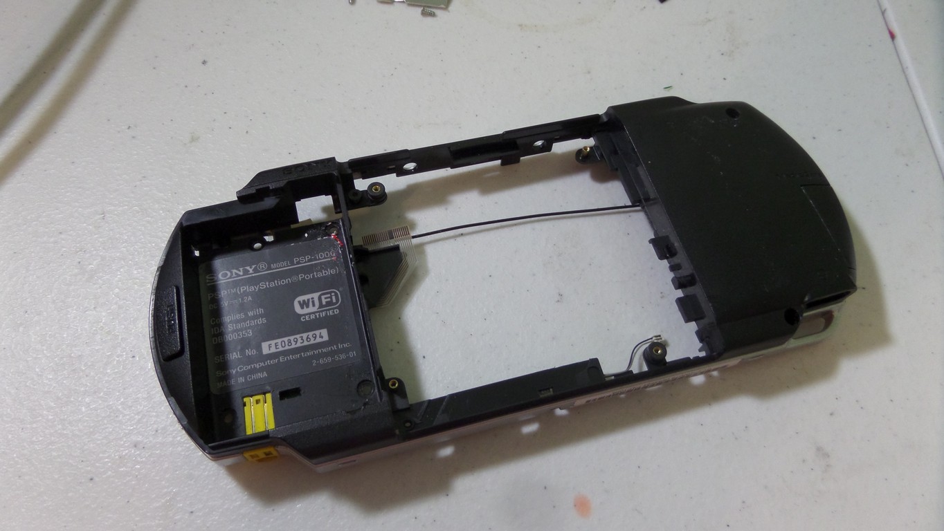
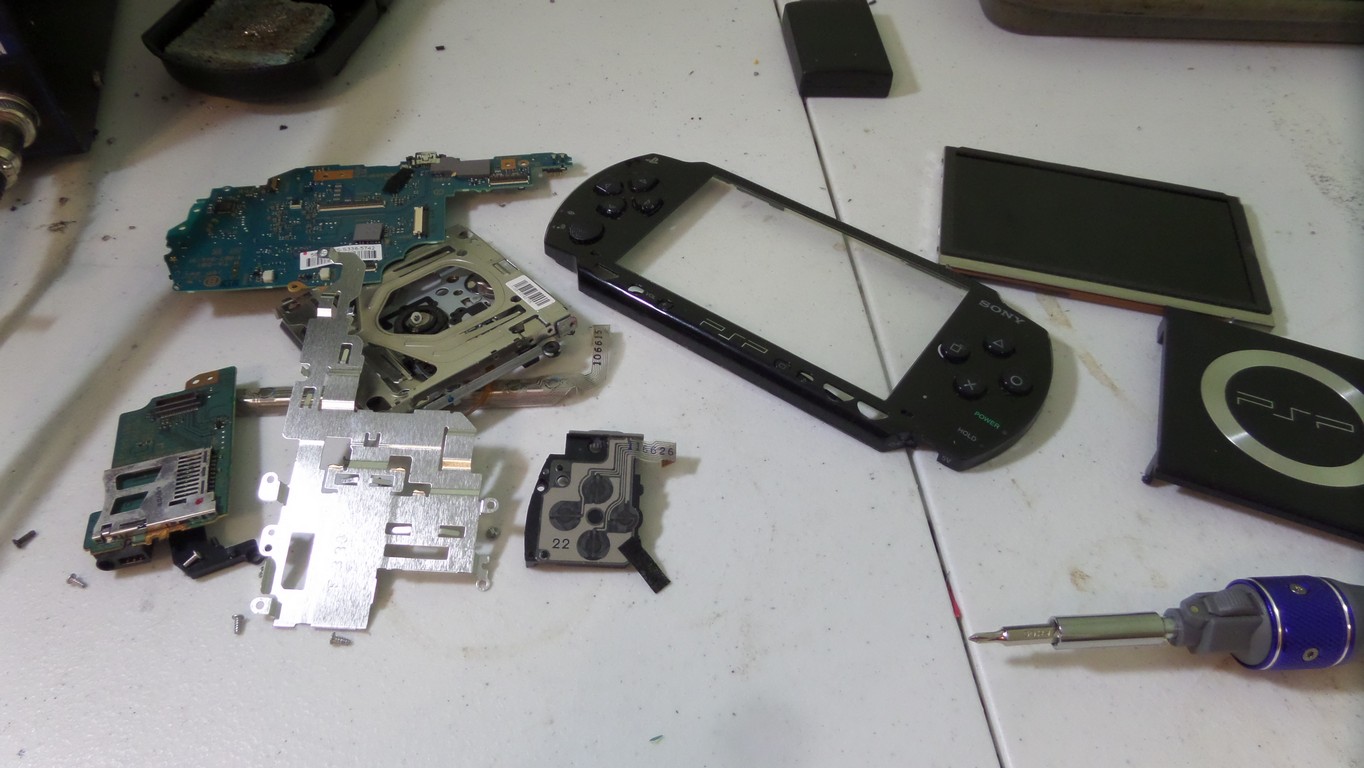
Teardown
The teardown process is straightforward. Some original internal parts will be reused.


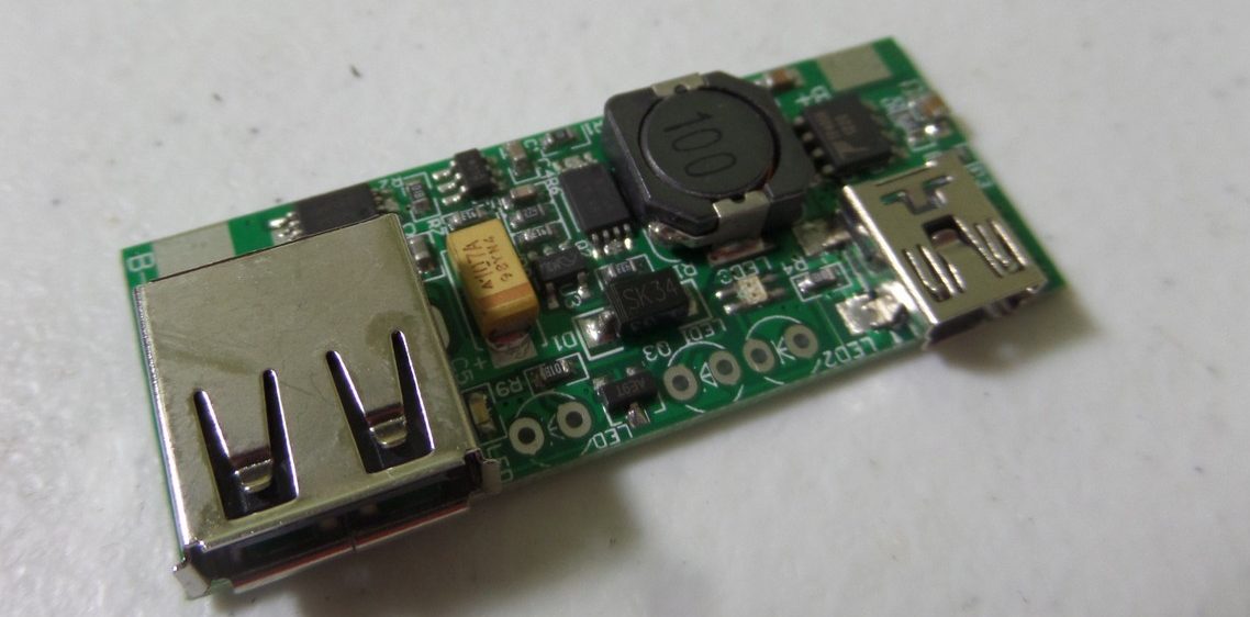
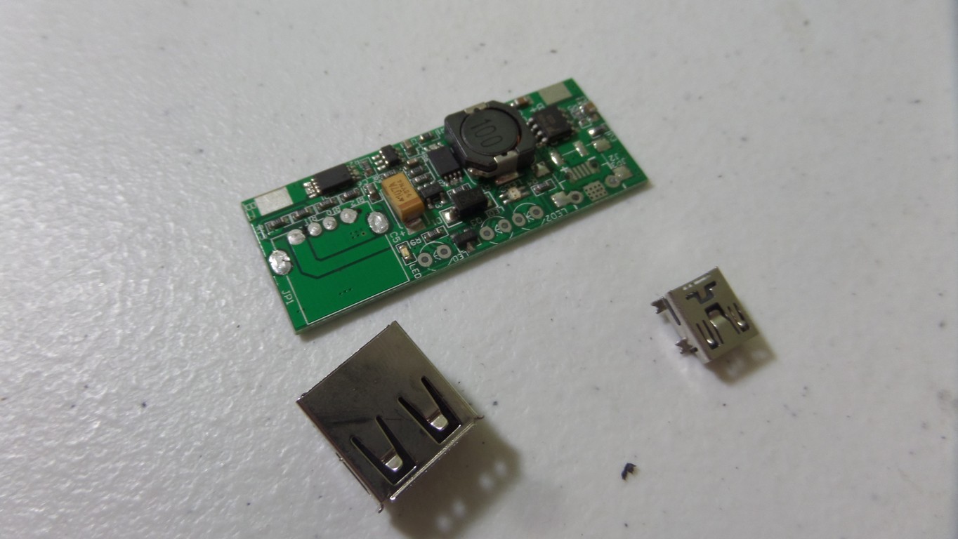
Power Supply and Lithium Charge Controller Board Install
The power supply board handles 5v power in, 5v power out, and 3.7v lithium battery charging. The USB connectors have to be removed so everything will fit. Also, some case plastics need to be ground down to make room. For more information on how this board works, check out the lithium power supply tutorial.


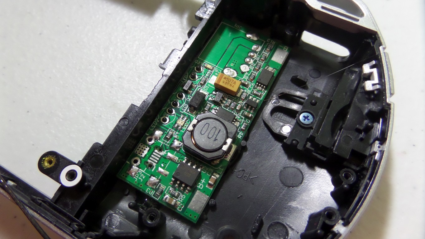

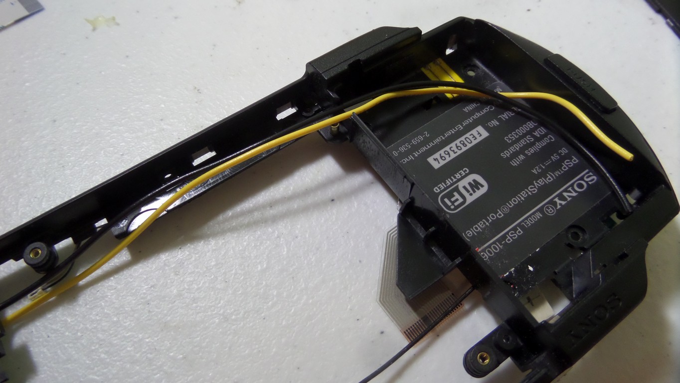
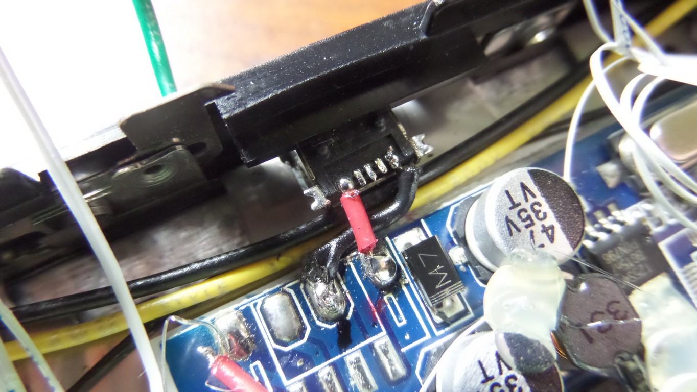
I reused the headphone jack from the old PSP board. A rework machine does the removal job well. The headphone jack will not be functional in this version. It is not wired in a way that allows the speakers to be disconnected, so it has little purpose right now. This might be something added to the next version. Here is the jack hot glued back in its original location.


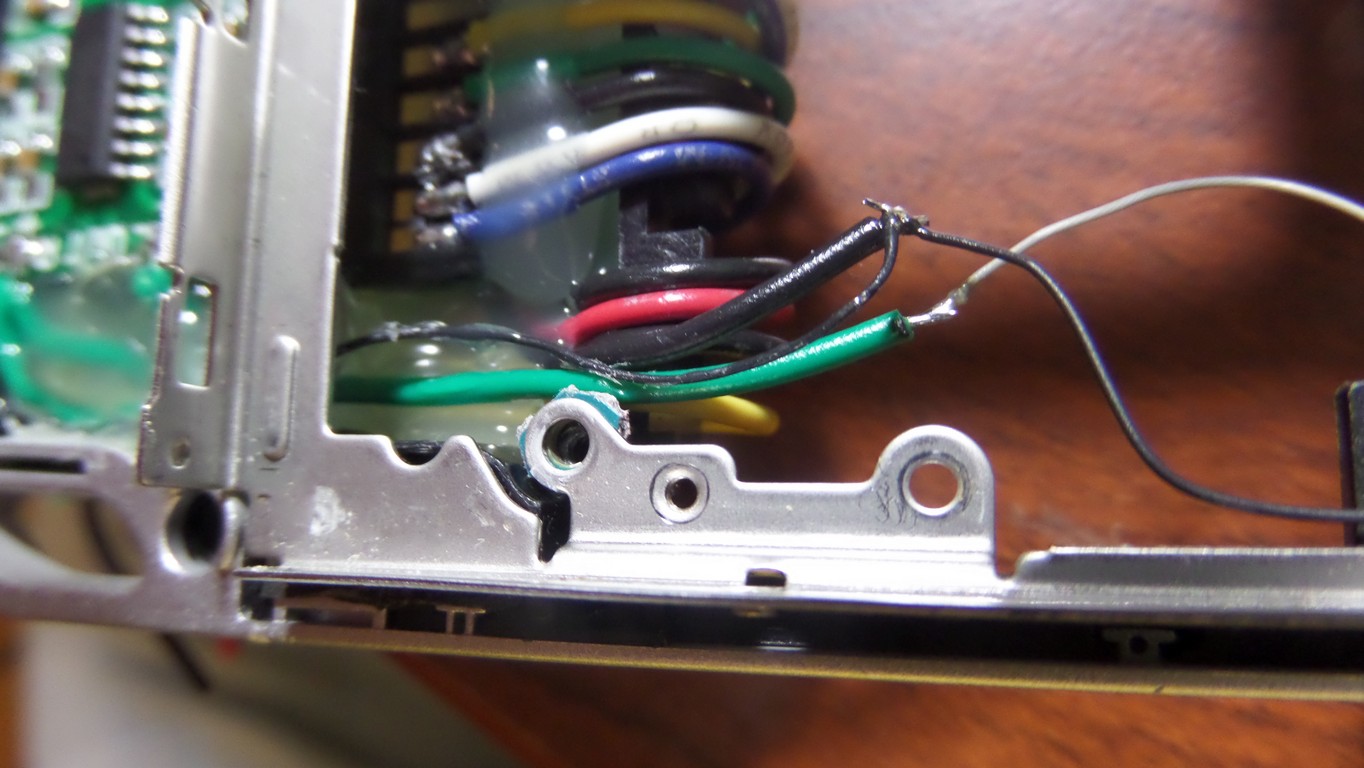
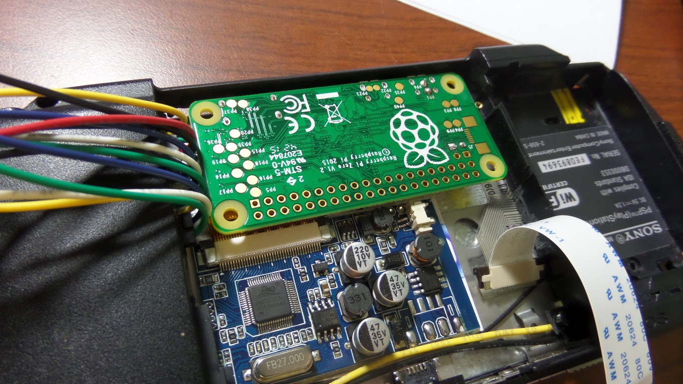
Running the yellow/black battery and the power input wires and the red/black power output wire. The green/black wires to the headphone jack are unnecessary and will not be used on this build. A ground wire should be soldered from the power output as shown in the last picture. This will be used for the audio amplifier.


Audio and MicroSD Wiring
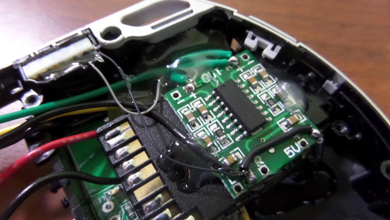
SD to MicroSD adapter are glued into position and audio amp is set in place. Adding solder to the SD adapter in prep for soldering wires. Soldering wires to the amplifier. The green wires are the left and right positive outputs going to the speakers. The negative wires from the speakers are joined together and soldered directly to the GND on the output of the power board, and the GND is also connected to the GND for the power and speaker inputs on the amplifier. The audio circuit is explained here. The additional audio filter components will be added later.


It’s time to start wiring the MicroSD adapter. I made the wires long because I hadn’t decided which direction I was mounting the Pi Zero. I ran hot glue along the wires to keep them from moving. Notice that one pin on the SD card is not used. Different colors were used so it will be easier to solder to the Pi later. For more information on how the microSD wiring works, check out the external microSD guide here.


Modifications
Test fitting the LCD bracket. Everything fits nicely and the wires are routed properly. The bracket has to be modified to make room for the LCD driver and for later modification of the joystick

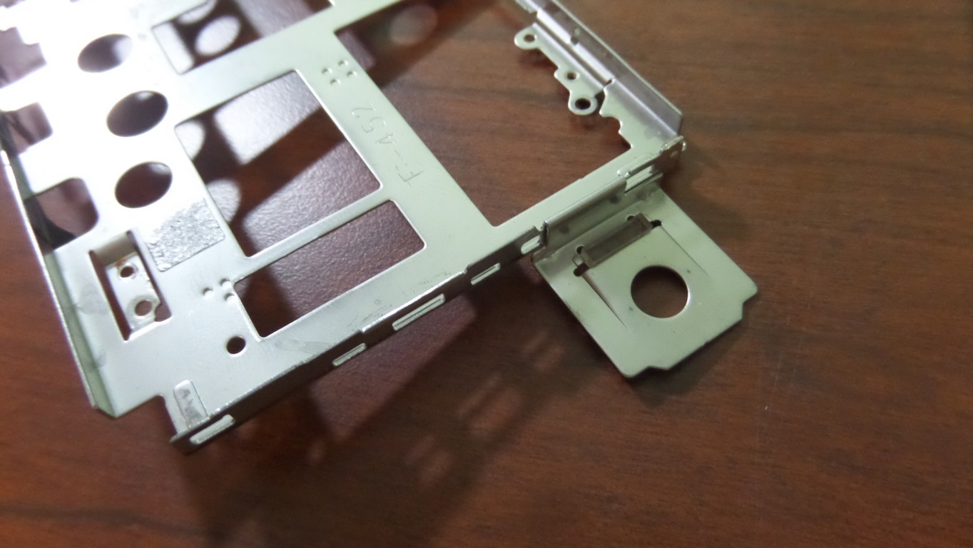


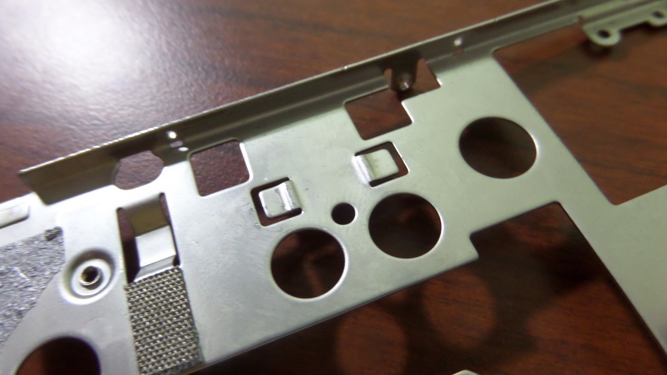
Modifying the plastics to make room for the new components


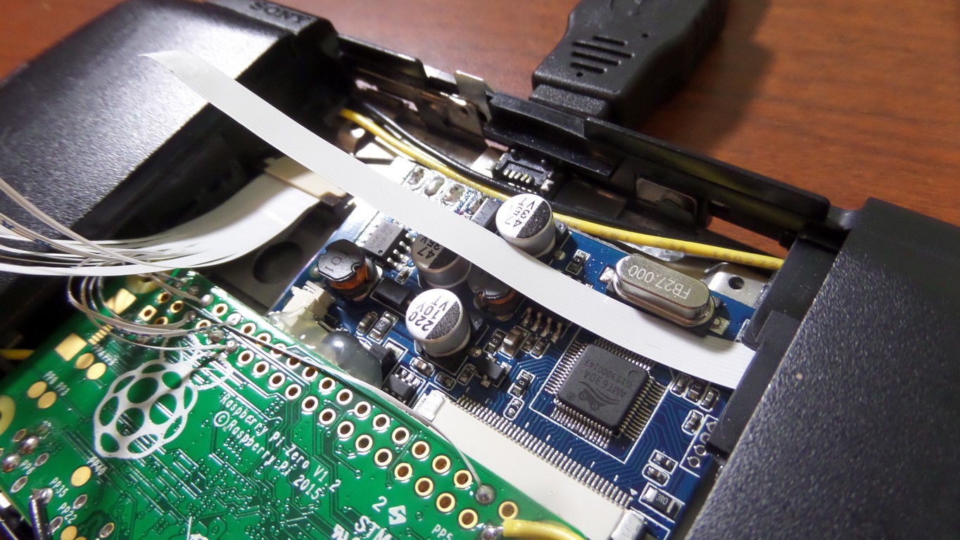
Here is the new FPC cable and the cable original to the PSP. The blue rigid plastic needs to be removed from the new 24-pin FPC cable. I could have ordered an FPC 24 extender for $5-10, but this $0.10 cable does the trick by sandwiching the contacts together and it takes up no extra space. I had to be careful not to bend the contacts on the new cable. I did this by pushing the new cable into the connector first, then pushing the PSP one in next. The connector is hard to close, and it squishes them together really hard. I know you’re asking why this cable is being installed. The explanation is later in the guide.


LCD and LCD Driver Installation
I’m about to mount the LCD bracket. It won’t sit correctly on the left side because the motherboard is no longer installed. It will crush the left trigger and keep it from working. It needs two spacers for the screws that are the thickness of the motherboard. So I cut out the small section of the dead board and used them.


Installing the other two LCD screws that are in the battery compartment


LCD installation and LCD driver. Make sure the LCD driver has insulation on the bottom, otherwise it’ll short out on the bracket. I used a piece of plastic cut to the size of the board.


Mini USB connector installation. Not being soldered yet.


Test fitting and doing a quick test of the Pi and LCD before I start soldering.


Soldering the MicroSD Port
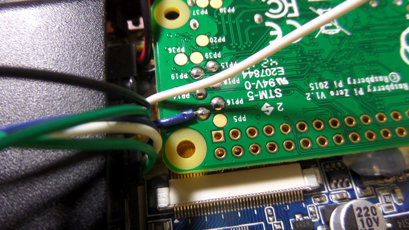
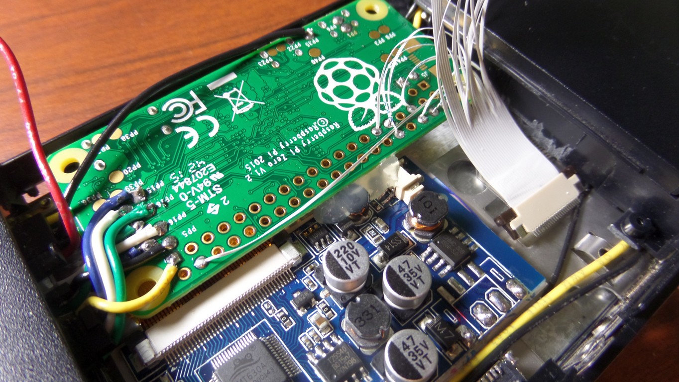
Soldering the MicroSD pins to the pads on the Pi Zero and soldering the ground wire from the power board to a ground pad on the Pi. Again, for more information on how the microSD wiring works, check out the external microSD guide here.


Battery Disassembly and Installation


This is a good time to do one more test to make sure everything still works after soldering the SD card wires.
FPC Cable Soldering
So we have a 24-pin FPC connector with contacts for the power/charge LED’s, power switches, and control buttons. We need a way to connect that to the Pi. Here is one solution.


Yes, you’re seeing that right. I’m using scissors to separate the individual wires on the cable, but a sharp knife works well too. I’m then soldering them directly to the GPIO on the Pi. There are multiple ground wires and I’m waiting until all other wires are soldered before soldering them. I’m going to bundle them together and solder them all at once.


So far I have the right side controls (circle, triangle, square, x) along with start and select soldered in place. The 5v LED power wire soldered up is also soldered up and the ground wire for the green power LED is going to be soldered to GND along with all the other GND wires. The LED’s can be powered directly by 5v because there are resistors already on the original PSP board (it’s like Sony knew I would want to do this)
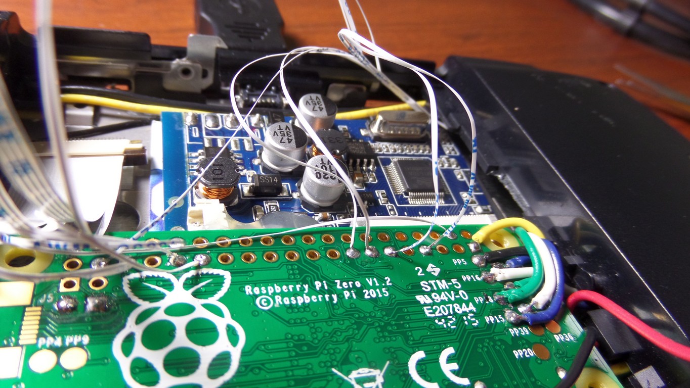
Here are three important photos you will need to solder the GPIO wires in place. It will be your choice on which GPIO pins to use, and your software needs to be configured to look for input on each GPIO pin. Most of the GPIO pins are used up by the controls.


The R Trigger is the far right pin on the FPC connector in the photo above. The GPIO pinout is modified to match the orientation of the Pi Zero when its flipped upside down and mounted the way I have it.
Now it’s time to start on the left side controls. This is going to happen exactly how the right side controls did, except with a 10-pin FPC cable instead of a 24-pin. Once the wires are sandwiched together, the white FPC cable is routed to the motherboard compartment and the control board is clipped into position. Again, the wires must be separated and soldered individually.


Soft Power On/Off Circuit
For a detailed explanation, check out the power circuit tutorial.
Now that the controls are soldered it’s time for a power-on test. It is also a good time to build and test the power-on/power-off circuit. It’s a dual-mosfet (positive and negative) circuit. Pushing a momentary switch turns the power on.
This starts with a dual diode. I chose the BAT54C because it has the right characteristics. Basically it is 2 diodes with the cathodes connected together. This is needed because the power switch has two functions…it powers on the Pi by supplying GND to the P-channel mosfet gate, and it powers off the Pi using GPIO. The dual diode keeps the two functions from affecting each other. You don’t have to use a single component here. Soldering two separate diodes works just as well.
Here is the dual diode component soldered to the GPIO pin and to the power switch. The switch connects to ground when pushed. Before I build the full power circuit, I’m routing the wires a little better.

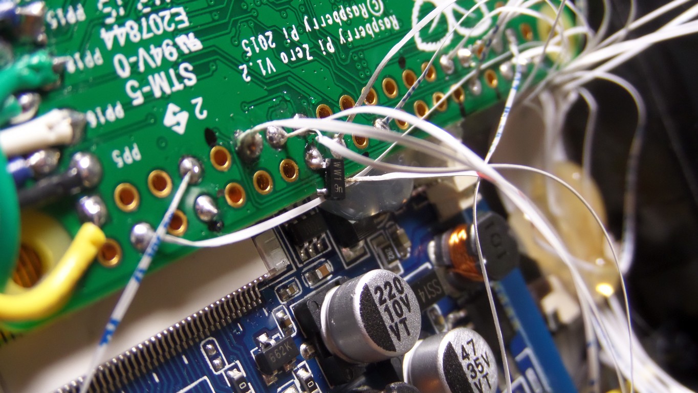


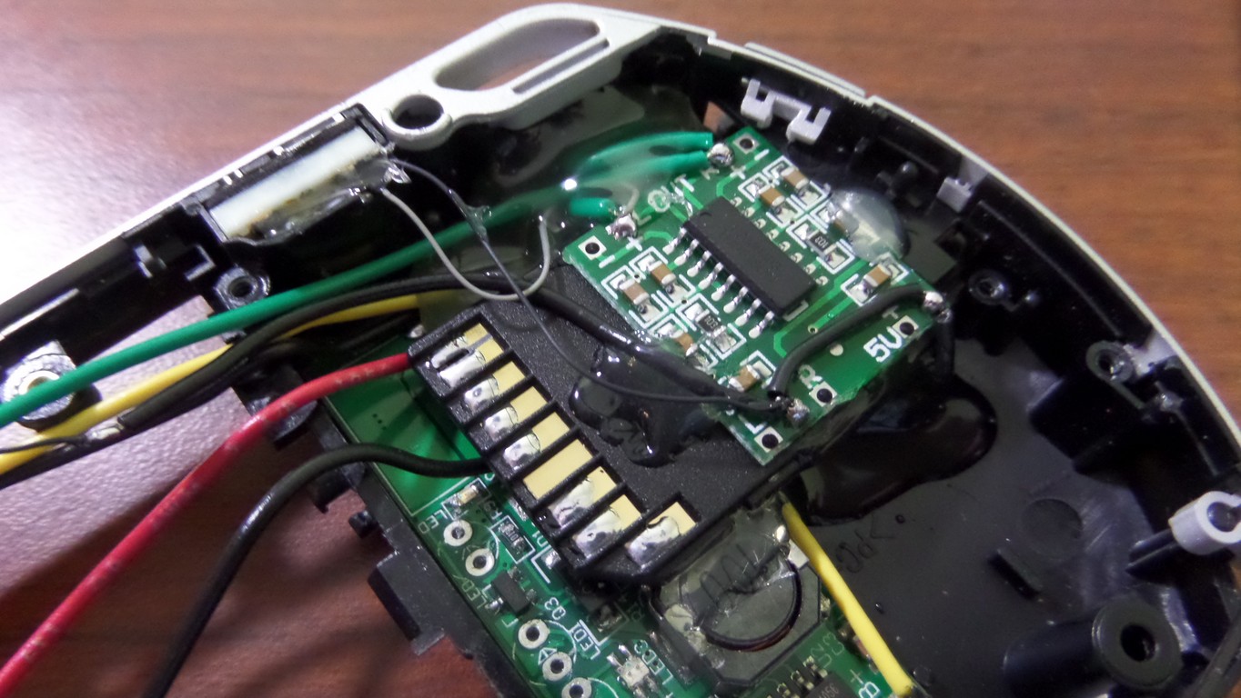
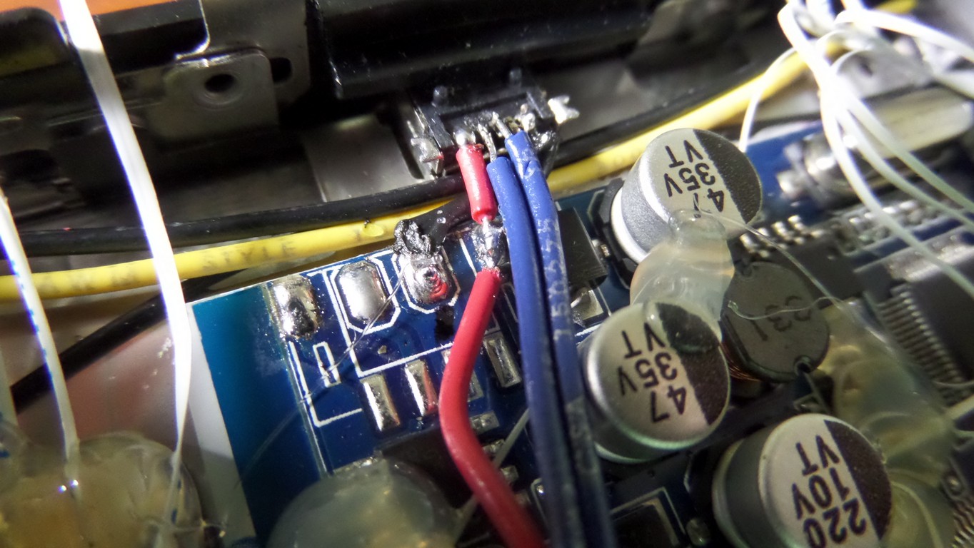
 And here is what makes all the magic happen, the IRF7319 dual mosfet. The left half is an N-channel mosfet and the right side is a P-channel mosfet. Earlier in the guide the GND wire from the lithium power supply got soldered directly to a pad on the Pi. The positive side is the part that will get switched on and off.[spacer height=”1px”]
The circuit works like this:
The +5v wire runs from the power supple to the input on the P-channel mosfet, and the output from the mosfet runs to the Pi. Power is only supplied when the gate on the mosfet is connected to ground. When the power button is pushed, the ground connects to the gate of the P-channel mosfet and power is supplied to the Pi.
The problem is that this will only keep the system powered as long as the button is held. This is where the other half of the component comes in… the N-channel mosfet. This mosfet works opposite of the P-channel, and has a negative input and output with a positive gate. Current only flows when the gate is positive. The output is connected to the gate on the P-channel mosfet.
 Here is the output of the N-channel connected to the gate on the P-channel. The two pins on the top-right side are N-channel outputs and are internally connected together. It doesn’t matter which one you use. The bottom-left is the P-channel gate.[spacer height=”1px”]
 The next wire to solder is the +5v power input. It goes on the pin above the gate.[spacer height=”1px”]
 It’s very hard to see below, but a 300k ohm resistor is soldered between the gate and +5v input. This keeps the gate at +5v normally and keeps the mosfet from turning on due to electrical fields nearby. You don’t have to use an SMD resistor. I used one for the small size.[spacer height=”1px”]
 Next to be soldered is the power switch. The blue wire goes from the gate of the P-channel mosfet to the other side of the dual diode.[spacer height=”1px”]
 And now the +5v output is wired to the Pi power input. If the resistor wasn’t soldered right now, there would be a 50/50 chance that the Pi would have powered on when I soldered it in place. The resistor keeps that from happening.[spacer height=”1px”]
Now for the rest of the circuit. As it sits right now, pushing the power button turns the Pi on, but as soon as the button is released the resistor will bring the gate back to +5v and the power will be cut off. It needs something to keep the gate connected to ground. The N-channel mosfet performs this task.
The ground wire is soldered from the ground on the Pi to the top-left pin on the component, which is the input for the N-channel mosfet. The output from the N-channel is already run to the gate of the P-channel, and now we need something positive to turn on the N-channel. The TXD pin on the Pi is perfect for this because it goes positive as soon as the OS starts booting. Not only that, but is switches to ground when the “sudo poweroff” command is run. This means that the Pi is completely powered off when the shutdown command is run. In this configuration, the power button needs to be held for about two seconds for the Pi to stay powered on.
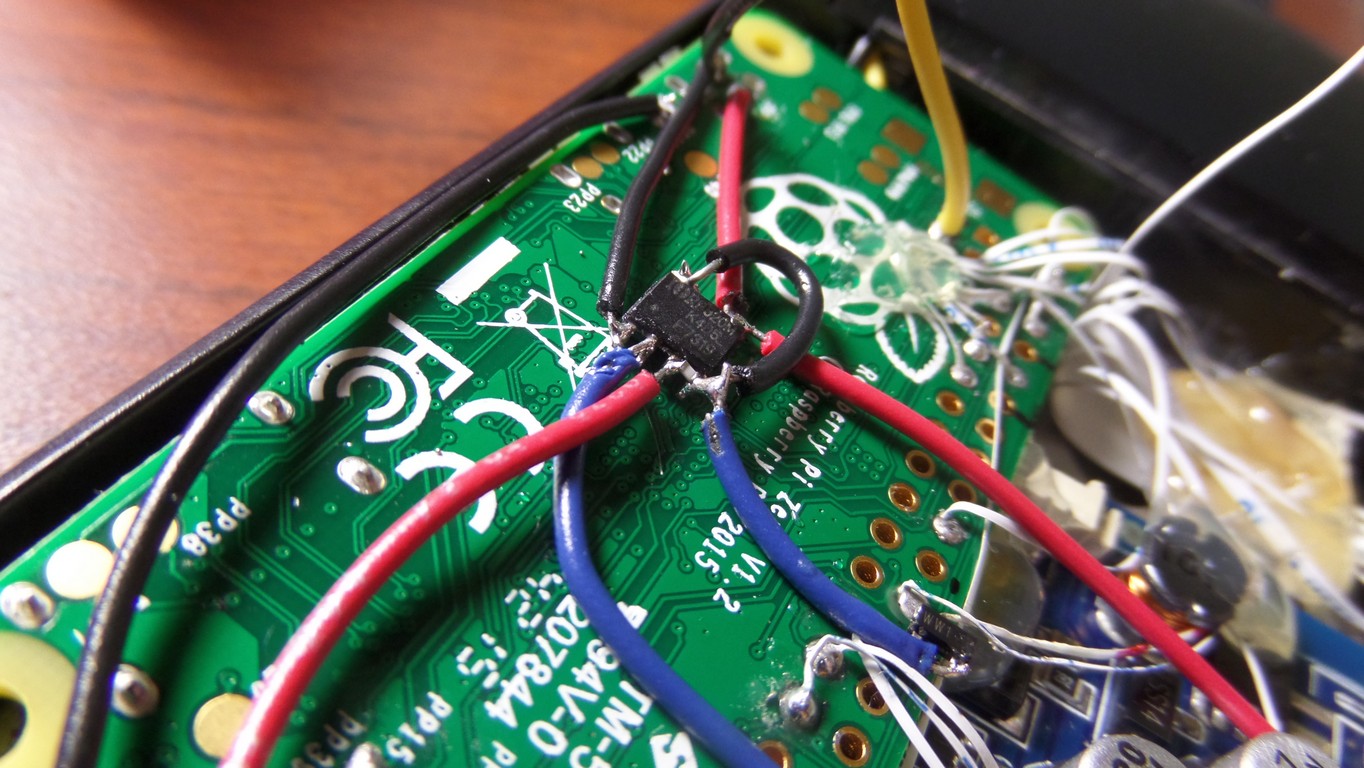 The second blue wire runs from the gate of the N-channel to the TXD pin on the Pi.[spacer height=”1px”]
 There is one more component to solder in place to complete this. We need one more 300k ohm resistor and it goes between the N-mosfet gate and GND. This resistor drops the voltage of the gate down to zero as soon as the Pi shuts down and kills power to the rest of the circuit. The Pi will power off and no power will be drawn.[spacer height=”1px”]
Now the system can be fully powered off by running the shutdown command. Pressing start in EmulationStation and selecting Quit and Shutdown will accomplish this, but who wants to do all that? A button is easier. The same button that turns it on also turning it off is much easier.
The other end of the dual diode is soldered to a GPIO pin, and when software detects falling voltage (which is what happens when the power button is pressed) the software issues the shutdown command. This allows the system to be shut off at the push of a switch, no matter what is running.
So that’s all there is to the power on/off circuit. I used surface mount components to save space, but standard ones will work fine.
Soldering the USB Port
A MiniUSB port has 5 pins, but only 4 are used. Here is the +5v wire being soldered from the LCD controller to the +5v pin on the port and the ground wire being soldered in the same way.

The first USB data pad is PP22 on the Pi Zero, and it is D+ and gets soldered to this pin on the USB connector


The other pad is PP23, and is D- and gets soldered right next to the other one on the Pi


Now for the +5v, GND, and composite video wires coming from the Pi. I should have done this before soldering the data cables. Better late than never.


One more ground wire is getting soldered to the LCD driver. It’s about to be used to solder all the ground wires from the FPC 24 cable. Until now, they have just been tied together. This is being done now because after the next step there is no going back. All the ground wires from both FPC cables join together now and are soldered to the ground wire coming from the LCD driver.


And the point of no return. This hot glue secures everything in place, keeping the USB port from moving when a cable is plugged in. Make sure you test the USB before doing this, since it’ll be really hard to fix those wires once the area is filled with glue.
Audio Filters
The next step is the audio filter. The guide is complete and available here.
150 ohm resistors are soldered between the ground and the L and R audio inputs. Then, the 10uF tantalum capacitors are soldered to the L and R inputs. The green wires come from GPIO pins 13 and 18 and solder to the capacitors. This completes the High Pass Filter. The Low Pass Filter is soldered to the amplifier output, and consists of a 270 ohm resistor soldered in line and a 33nF capacitor connected between the positive audio outputs and GND.


Low Battery Circuit
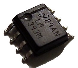 We are nearing completion with only a few more pieces to install. The low battery warning LED is next. At it’s heart is the LM393 voltage comparator, which compares two voltages and switches an output to either 5v or GND depending on which input voltage is higher. The function is explained in detail on the Low Battery Warning Circuit tutorial.[spacer height=”20px”]
We need a way of knowing the lithium battery is close to being depleted, so we compare the lithium voltage to a stable voltage.
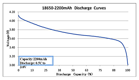
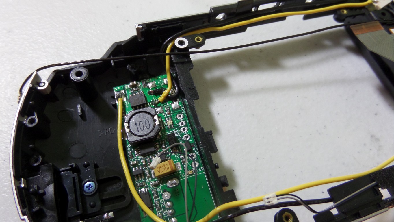
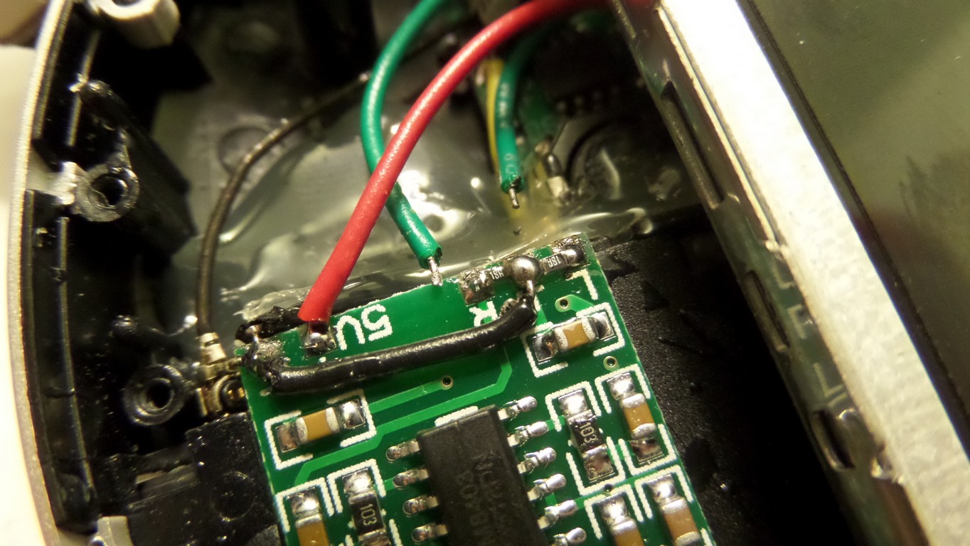
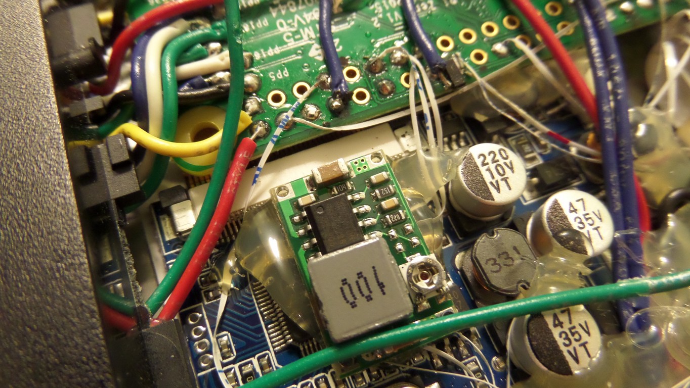
This image shows the discharge curve of a lithium battery. When it reaches 3.6v it’s at about 20% capacity, so that’s a good voltage for a warning light. For this circuit to work, we need to generate a stable 3.6v so we have something to compare against the battery voltage. There are many ways of doing this, and in this situation I used a buck converter.[spacer height=”20px”]

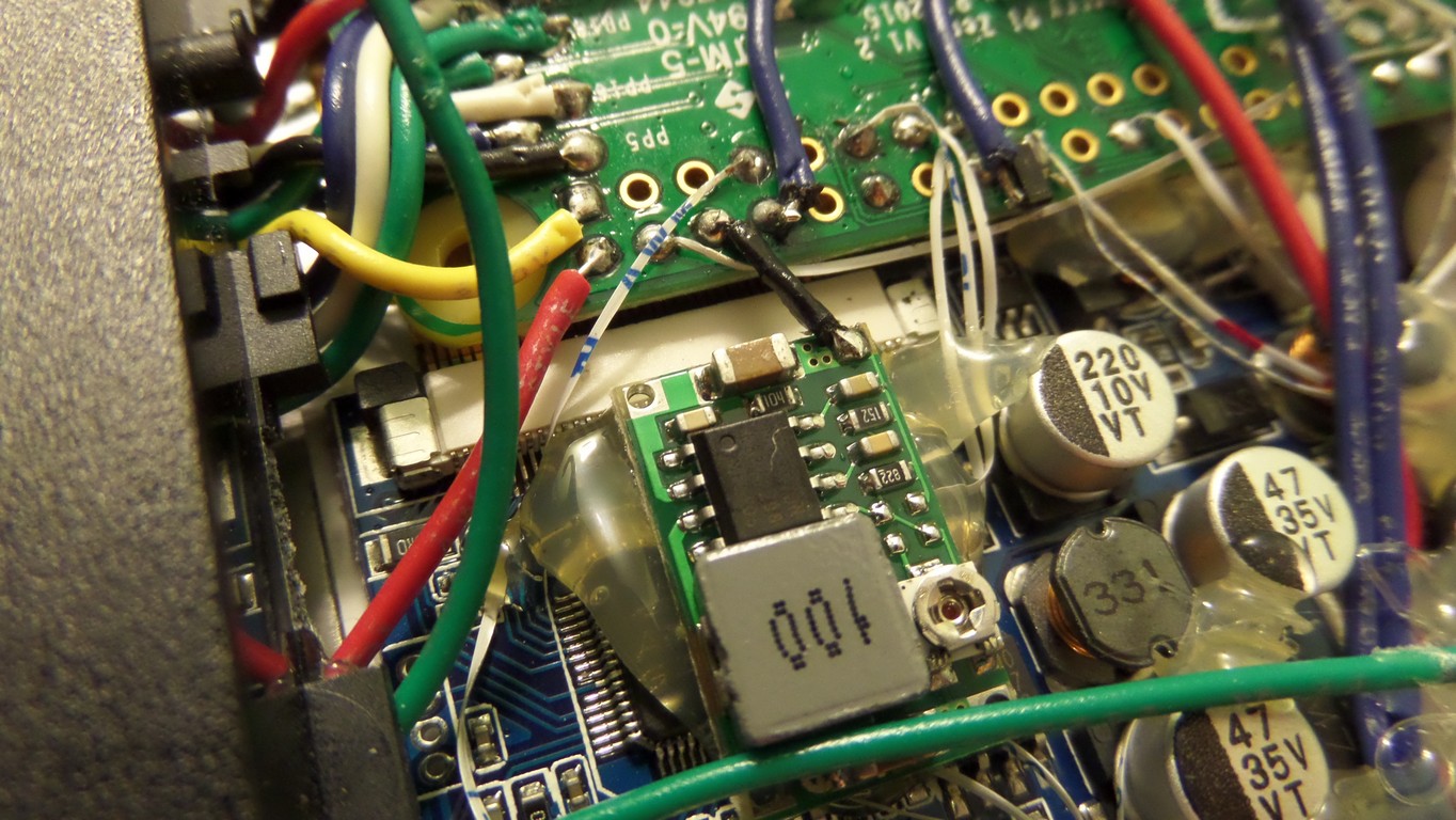
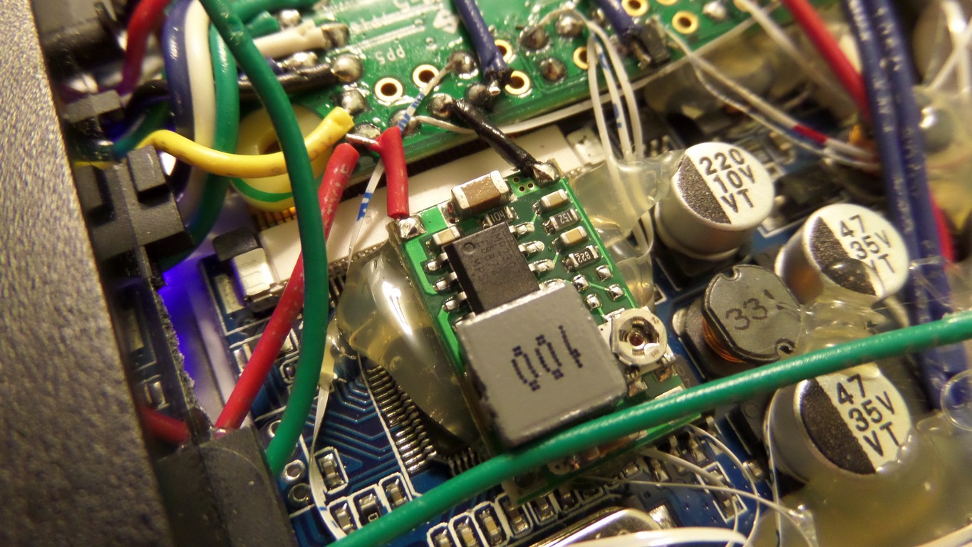
The buck converter is glued into place and the 5v and ground wires are soldered to the inputs. The variable resistor is adjusted until the output reaches 3.6v, or whatever you prefer your low battery warning voltage to be. The LM393 is then set on top of the buck converter to prepare for soldering. If you look at the 4th pic, you can see it glued into place.[spacer height=”20px”]


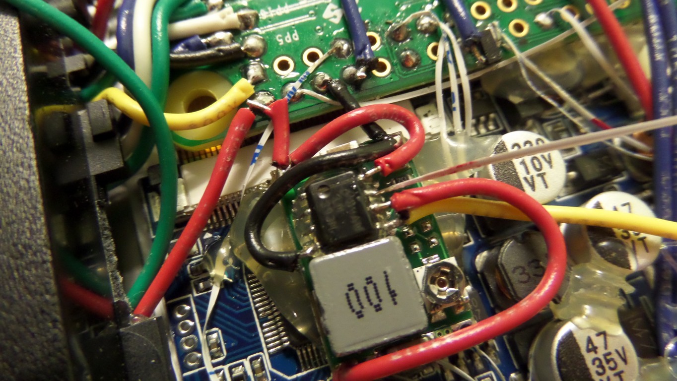


I made a few changes to the low battery circuit. The LED now lights when the Pi is off and the charger is connected, giving an indication of charge status.
 Plugged in and charging[spacer height=”1px”]

Plugged in and fully charged[spacer height=”1px”]
 Off and not plugged into a charger[spacer height=”1px”]
So I’m calling the hardware side complete. I was going to add the joystick circuit, but I’ve chosen to add it to the next PSPi. I’ve got some changes to make to the software on this, then I’ll start on the next one.
Good luck with your project!
Hmm, good progress, do you know the approx thickness of all the circuit parts that you put into the psp? Im thinking of doing the same-ish thing but with a ps vita 1000 case, it is not as thick as the psp 1000 (0.73 inches compared to 0.91) but it has more horizontal and vertical space. Cool project by the way!
I would estimate around 1/2″ for the components. The LCD bracket adds a little thickness, and I’m unsure whether the Vita has any brackets that need to be there.
I’m really excited that someone has done this already! I’m trying to follow your guide but I’m lost at the FPC cable wire soldering part (more of a software guy than a hardware one). Is it possible to provide a chart or diagram depicting where each wire is soldered on the Pi board? Great work nevertheless!
I agree that the FPC soldering is the most complicated part. I’ll see what I can do about making it more clear. I’ve been considering designing a circuit board that the FPC cable would connect to and that would solder directly to the Pi, and putting them up on eBay so people can use them. I could maybe even find a way to add all the power circuits to it. It’s very complicated, so I’m only willing to do it if enough people are interested.
This is a great idea. I’m sure that a lot of people will be interested in that as it’s one of the more compelling ras pi zero projects out there. But at least a diagram will be a start so that other people can follow along and maybe even come up with some recommendations
I would love that it would be a great help to lots of people.
I’d definitely be interested in a pcb rather than hacking up ribbon wiring! Scares me.
first of all I wanted to make you my compliments for this that I think is one of the most exciting projects I’ve ever seen !! i love to make it but I see very complicated, if there would be the possibility of a video tutorial would be great !! I look forward…….good work !!
Thank you for the compliments. It’s too late on this one, but the next one I build should have more videos showing the process. This one will be pictures and tutorials only. I’m close to being finished with Version 2. Its been put on hold for a little bit while I make tutorials for the various parts of the build, and I’ll be getting back to it soon.
Loving the work dude, been following you on the retropie forums and I’ve got all my project parts on order to follow your lead! Just wondering when the audio wiring is going to be documented as I’m intrigued as to your take on it? I’ve been reading up about the zeros pinout for audio so I get the gist of what’s involved, but I’m yet to experiment myself. Keep up the good work and I’m eager for the next update!
There were so many requests for tutorials that I decided to switch my focus to writing them instead of continuing the work. I expect to start working on it again by next weekend, so updates should come soon after.
Hey, I just wanted to say that this is so cool and i’m trying to do a project similar to it!
I was wondering if it was necessary to use the lithium batteries or would the old psp battery work just as well?
The PSP battery is rated for 3.6 volts, so the operating range for the voltage is slightly different. Using it with a 3.7 volt lithium controller could cause it to wear out faster, but yes it should work. That being said, I did some research on that and some people are saying that the current 3.6 volt batteries being made are really 3.7 volt and are just labeled as 3.6. I used the BlackBerry batteries because of the higher capacity and low price, but I’m fairly sure the original battery will get the job done.
Thanks for this well documented guide. Got my first zero on the way and I’m snooping around for a dead PSP to start moding around.
Do you think there is enough space on a PSP 2000 or 3000 for this mod?
I was wondering the same thing, so I ordered broken 2000 and 3000 versions to find out. It’s not my highest priority right now, but I will be taking them apart at some point to investigate.
First part arived. It is display. I have PSP 3000 and the display I order fit just PERFECTLY. It is awesome. So yes, there might be enough space in psp 3000.
That’s very promising. Have you tried fitting the LCD controller and Pi in there yet?
I was about to ask the same question. I have a working PSP 3001 but I’d like to turn it into a PSPi Zero to have more power and game stability. I’m analysing the whole process and I’ll provide all the needed parts to have this done, but it’s a priority right now. Since Brazil doesn’t have to much access to parts like that, I’ll order some and wait until I have them all.
But that’s a very nice project though, congrats.
So very, very cool!
How do you power the TFT? Usually those things need 6V+ to light up, right?
Some of them work as low as 4v. The $14.99 ones on Amazon do great. Right now my favorite is the one here on eBay
Oh nice, thanks! Is this the same one you are using for this build?
Yep. It’s my favorite so far. Seems to use a little less power than the others.
What the heck I’m going for one. I know I have an old PSP in a closet somewhere, and this build is just too irresistable.
Thanks a bunch for writing such in-depth tutorials, and respond with direct advice on top of that!
Hey, from the look of your low battery pics the lm393 is glued to the top of the buck converter, is that right? Are the pins from that chip soldered to the buck’s chip or is it purely just for space saving?
Space saving only. I’m still working on the details for that part, so I hadn’t clarified it yet. Yes, the chip is sitting on top of the buck converter because it was the perfect place for it. Some pics are coming soon to show that they are two separate parts and that I’m not soldering to the 8-pin component on the buck converter.
I can definitely see why you were asking.
Thanks for the clarification, I’m currently stocking up on the parts for my copy project so it’s great that you’re documenting this so excellently. Keep up the good work my friend, I can’t wait to get stuck into my version of this.
I stumbled upon the videos of your version 1 on youtube and followed them here. this is exactly the type of pi project i had in mind as im always on the go and don’t have time to sit and game in front of the tv.
unfortunately like others have said here; im more of a software person rather than hardware and my soldering skills are lacking so im not sure i’d be much good following along with your guide. BUT! I wanted to say, keep up the awesome work, man!
Thanks for checking out the project. I know there are a few Pi projects that require far less soldering, something like this one Adafruit makes that’s ready to assemble:
http://www.ebay.com/itm/Adafruit-GameBoy-PiGRRL-2-Complete-kit-Raspberry-Pi-3-Pick-Your-Color-Combo-/162125650232?_trksid=p2352135.m2548.l4275
or this completed project:
http://www.ebay.com/itm/Raspberry-Pi-Zero-Gameboy-Casemod-with-2-Removeable-Batteries-Retropie-Emulator-/322197676894?hash=item4b047a635e%3Ag%3AKiUAAOSwOVpXZK7V&nma=true&si=QzagWsRiytkV9EH9ht7jvRvmksU%253D&orig_cvip=true&rt=nc&_trksid=p2047675.l2557
Personally I like mine more since the screen is bigger and the controls are easier to use.
Maybe I’ll consider raffling off the PSPi 2 or putting it on eBay once I get it finished…
I’m working my way through the FPC-24 and I feel like a hair dresser. Is burned PET toxic you think?
Cutting the FPC wasn’t half as bad as I thought it would be just using a razor and a magnifier, but that’s knowing before hand from you that it can be done. Really impressed that you came up with the idea to start with!
BTW, the 5V only connects to the LED’s, right? I am cheating using a Teensy LC, and that doesn’t like 5V on the GPIO (like as in “sad brown smoke”).
I’m laughing so hard at your comment. Correct, 5v only goes to pin 22 on this diagram, and both LEDs share the same 5v. It is also used for the Low Power LM393 Circuit, but that’s later on in the process.
Also, I recommend checking along the way that your FPC pins are connected right. For the buttons I used a voltmeter, connecting one side to ground and the other side to the FPC wire and tested pushing the button just to make sure a connection was made.
I did that with the LHS controls, but there seems to be some built in resistance? I got something like 100Ohms, but it’s enough to pull the input low on the Teensy. Maybe I should clean my leads in the sandwich end with some alcohol to make sure they are well connected… or it’s some PET goo still isolating in the solder joint…uugh..
I get 50-100 ohm on mine too after cleaning the contacts
Good to know, I was starting to worry that my GND connections were bad because I soldered a whole bunch of them together. Lots of plastic to burn off. Maybe I got in a little over my head for a first mod project…. 🙂
Have you thought of using something like this for the sd card ??
http://www.ebay.com/itm/142076977160?_trksid=p2055119.m1438.l2649&ssPageName=STRK%3AMEBIDX%3AIT
OR
http://goo.gl/I8wVDA
I am wondering if it could help save space
Also a random feature you could add since it is so slim is wireless charging using something like this
http://www.ebay.com/itm/For-Samsung-Nokia-HTC-Nexus-Hot-Qi-Wireless-Charger-Charging-Pad-Receiver-J-/391515627463?hash=item5b28265fc7:g:Qp4AAOSwdzVXlefH
What about the idea of bluetooth for headsets for sound? not sure if it may work better or not
a good usb hub for this would be
http://www.ebay.com/itm/Mini-4Port-Hub-High-Speed-USB2-0-HUB-Splitter-Cable-Adapter-for-Laptop-PC-Useful-/131842155271?hash=item1eb267a307:g:EOAAAOSwYHxWQqjN
all of the ends can easily be removed and left to just the board on the inside of this giving you a few more ports if needed
EX
http://forum.erlerobotics.com/uploads/default/51/92a77a094e19d39a.jpg
The reason I say adding usb….
*wifi
*bluetooth
*micro usb flash storage can be soldered in
*card reader could be added allowing you to interface with a second card and use the first one as internal only storage
*usb audio maybe
you could use something like this to transmit video/audio over to a tv if you wanted (would need to find a RX modual)
http://www.aliexpress.com/item/5-8GHz-TS5828-600mW-32-Channels-Mini-Wireless-A-V-Transmitting-TX-AV-Video-Output-Cable/32622597476.html?spm=2114.40010308.4.98.NaKBZB
sorry for all never ending this LOVE the project and cant wait to build my own already bought my pi and sd card waiting on some parts in the mail now 😀
Wow you have some good ideas here. I already tried the microSD Adapter but wasn’t happy with the fit of everything, and the SD to microSD option was very inexpensive. Wireless charging never even occurred to me, and you’ve got me curious. I’ll be doing some research on that tonight. The USB hub with all the USB devices is something I thought about doing. Maybe the next PSPi will have some of these additions crammed into it.
I like this! I am doing something half-way adding a 4-way stripped USB hub in the left compartment. This connects to a WIFI dongle, the miniB external, a USB sound card and a Teensy for the control wiring. The idea I had was that with the Pi powered down, you can use the PSP as a normal gamepad through the miniB with only the Teensy running.
With the Teensy I have 9 analog inputs that are very easy to program, so I was thinking of adding a 3D tilt/motion sensor to emulate a right-analog stick, or perhaps a steering wheel type thing. Need to work out how to trigger calibration though.
And of course hook the Display button on the psp to a pin on the Pi and trigger a tvservice script to switch between composite and hdmi output so you can hook it up to a TV using an hdmi cable that comes out through the old UMD hatch.
Why did you choose the batteries you did? The size/form factor? I’ve been trying to see about getting a good battery to do something like this but it’s a bit of a pain to find anything with good mah
I chose these because they were a perfect fit, and they weren’t some no-name Chinese batteries so I knew that they would have the watt-hour rating that was advertised. This wasn’t the only one I ordered though, I tried a bunch of different ones with similar specs and these just happened to be perfect.
after you perfect the psp would you look into making one with the psvita? would it be the same? the vita has two joysticks, would it be possible to connect both of those too.
It’s something I would consider. Since the Vita is based off an ARM CPU, it’s possible it’s already been hacked to allow many of these features. I haven’t researched it, so I’m not sure. It is possible to do multiple joysticks though, and one of the chips I’m using has inputs for two joysticks.
I have compiled a amazon list of all the products that you have indicated are needed for the project, with the exception of the pi zero. I have a few questions though. Do I need to buy a 8gb Micro SD card with adapter When the Pi kit indicated comes with the same one that you recommended? Second you indicated Miscellaneous Resistors and Capacitors in your parts list. Can I have a quantity and detailed list of what will be needed. My ultimate goal is to streamline the ordering process for people who want to take on this project by adding a link to the list of all the parts. So far as it stands without those resistors and capacitors the checkout total is $122 + The $25 for the Pi Zero Kit. On a side note do you feel PSPi version 3 will have a lower build cost with the addition of the boards that you are designing or will they not affect the bottom line. Sorry for the long winded question buy I am really interested in this project but am on a tight budget.
1.) When I put that list together the Pi Zero was going in and out of stock. I put both the kit and the SD card just so people had options. So the answer to the first questions is no, you don’t need both.
2.) I can probably put a list together of all the resistors and capacitors. The big problem I have with a single link is that these parts keep going out of stock on Amazon. I’ve had to go in a few times already and update links. That’s the reason most of my links now send you to an Amazon or eBay search for an item instead of to a specific item.
3.) Cost really depends on where the components are being ordered from. Amazon’s prices tend to be higher, but eBay’s shipping times are slower because the parts usually come from China. When I sell the board, the parts I use will be purchased in large quantity and the component price will be lower, so I expect the price to be either the same or lower.
4.) I have a different idea. Since I’ve got all the components here already, would anyone like it if I sold a complete component kit?
What would the cost be? That sounds like a good Idea for those people who “i am going to do this right now!” as for me (unless the price is significantly better than buying individually) i may just buy the components in batches as to not take a big chunk out of my bank account at one shot. I have been looking for this project since i started playing with Raspberry Pi, but I am a reasonably new hobbyist so i don’t have these components at my disposal and all the radio shacks closed in my area 🙁 . I am really interested in the custom boards though for the neatness of the project. what components can i put off purchasing in place of those boards. is there a benefit to changing the screen or can i use the original?
It will take me some time to do the math. I’ll let you know a price soon.
Almost everything will be included in the board. That pretty much just leaves the Pi itself, LCD, SD card, power module, audio amplifier, and some wires.
The original LCD cannot be used because there isn’t a small enough board available yet that can drive it. The long-term goal is to find a way to use it.
so far the only board that i found is this one https://sites.google.com/site/fpgaandco/de0-nano-psp-screen have you seen others if so can you provide links i may be able to achieve this with a custom backplate but i am unsure i am waiting for my pspgo to get here from brazil ebay seller.
Hey othermod I just wanted to take this time to say how much this post has inspired me to work towards this project I really am excited and now I am fully intend on going forward with the PSP Go version I feel with a lot of tinkering I could get this thing to work I may have to redesign that board in the previous post but I’ve never done anything like this so we’ll see how it goes I have a few friends that are going to help me but I think we should be able to manage it I might just have to save a little room off the hard part is going to be soldering all those connections and I’m sure you can feel my pain
I’m happy to help if you have any questions along the way. I look forward to seeing what you make.
Any idea if this would work with a psp go I like the smaller form factor
It probably isn’t doable with the devices we have available right now.
Hello, your project is awesome! Couple years ago i had a similar idea but i was a noobs in hacking stuff. Yesterdays i fall on your website with the help of good luck 🙂 and right aways i just finish to get a raspi2 and a subtronic X300 in the psp 2001 shell. It was a ruff days but it will be worth it. Thank a lot for all your detail.
Wow.. One of the best tutorials I have ever seen.. Great job!! Definitely a bookmark.
Is there any possible way to fit a Pi3 inside? I saw it done with a GameBoy by removing connectors, etc.
Thanks for the compliments. I haven’t tried the Pi3 myself, but a few others have asked and at least one of them might be trying it. The clearances would be tight.
This is an amazing guide, thank you for your ha d work. I do have one question, why is the original psp screen replaced with a different one? Is it the connection type? Or quality of the screen? ie resolution.
It’s because there was no good controller available that could drive the original screen. I’m working toward using HDMI and possibly using the original screen, but that’s a slow-moving side project. Most of my focus is on getting the kits ready.
Any update on a way to add in the wireless charging? It looks like it could be pretty straight forward. I am getting ready to start building this and would like to add the wireless charging mentioned by xx0m3gaxx, if possible.
I’m working on it soon. Once the FPC-24 board gets here I’m doing a build so everyone buying the 1000.2.1 kit has a guide to use. I’m adding wireless charging to it.
Are you planning on using the same or similar receiver? If so I will go ahead and get mine ordered. I plan on ordering the FPC-24 board from you also once they show in stock, since I went ahead and ordered everything else from you yesterday. 🙂
I’m using this. I tested to verify that it functions, but haven’t done much beyond that yet.
I appreciate the order. Everything was fully tested so I don’t expect issues, but please let me know if you do have any. The FPC-24 board shouldn’t take much longer. Fabrication should be finished any day now, and it takes about 2-3 days for me to get it once that’s done.
othermod I like your project.
I am planing to build it, but can you please tell me the connection of bat54-c(I meant which gpio pin and tell which the other wire).
The single side goes to the switch, the the switch connects to GND. The first wire on the other side goes to the mosfets for powering it on. The other wire can go to any GPIO pin that’s available. Software can run in the background that can look for the button to be pressed, and the code can be adjusted so that it looks at any pin you specify.
How do hook up the power switch? Do I take the switch from the old board?
The switch stays on the PSP’s right-side controls board. You just connect to the pin on the FPC cable (using either by FPC-24 breakout connector or by splitting an FPC cable).
Would a psp 1003 work or does it have to be a 1000?
Thanks
Any PSP in the 1000 series, as long as it’s the original fat one.
Could you please explain a little more on the audio board. Where to I connect the black thin speak wires too ? I connected them together but where do I connect them too? Could you provide more pictures maybe?
I’m struggling a bit around here as well. The pictures appear to change:
http://othermod.com/wp-content/uploads/2016/07/SAM_0329.jpg
vs
http://othermod.com/wp-content/uploads/2016/07/SAM_0342.jpg
In the latter picture it seems like an additional ground wire has been added?
I believe that I originally intended to route that ground to power the Pi or LCD, but decided not to. It’s been a long time since I built this and I’m not 100% sure. As long as you share the same ground between everything you’ll be fine.
I’ve bitten way more than I can chew but it’s been fun so far. I assume you can’t power on the Pi without a battery attached to the charge module (USB charge light on but not battery attached)?
I’ve checked with the volt meter and when the charge module is plugged in it does output 5v via the output power wires although this doesn’t seem capable of turning on the Pi. I notice in your test example you’ve got another charge module and a single battery attached to that :S
Yeah, the module needs the battery installed or it isn’t stable. The boost chip needs bursts of power, and the 5v input can’t provide that
Thanks! It works with a battery 🙂
Also, thank you very much for this guide 🙂
Hello,
(I tried to message this but i don’t think it sent)
I am hoping to build one of your PSPi 1000 version 2, since I have no experience soldering PCBs, otherwise I would make version 4. However I have made many electronic projects and have also spent many hours configuring retro pi in many different ways. I can read schematics and solder boards just fine, but I have never assembled a PCB and try to avoid doing so. I have some questions, though, before I start.
First I was wondering if this tutorial would allow me to add a joystick as if it were a few more buttons. http://othermod.com/analog-joystick-on-retropie/ Or if this one would do the same thing. http://othermod.com/simple-joystick-using-lm339/
Second I was wondering if I could and if so, how to add this circuit to version 2 or if it was already added.
http://othermod.com/raspberry-pi-low-battery-warning-led-circuit/
Thirdly I noticed the only board that you still carry for version 4 is the headphone board. I was wondering if this could be used in creating version 2 since it seems to put a bunch of the same components on one board. I would not ask other than the fact that the pin out is not marked thus I can not tell. If it will work would you be so kind as to give me what each color is, too.
Thank you for any help you can provide
Just so i can get a couple things clarified, the power and charge led wires both get soldered to ground correct?
And the switch pin wires 1 and 4 get soldered where exactly?