

Simple Joystick Using LM339
This tutorial describes one method of adding joystick function to your Raspberry Pi projects. This is the simplest method to set up, and it uses the same software as GPIO buttons.
To purchase a complete board or to make your own, visit the product page.
 The LM339 is at the center of guide. It’s a quad-channel voltage comparator, and works similarly to the LM393 used in the Low-Battery guide. It compares two voltages, and switches an output to GND.
The output PIN switches to GND when the voltage on the positive input pin is higher than the voltage on the negative input pin
When the voltage on the positive input pin is lower than the voltage on the negative input pin, the output is not connected to anything and is just floating. [spacer height=”1px”]
So how do we put this to use for a joystick? An analog joystick works just like two variable resistors, one for X-axis and one for Y-axis, and the resistors divide the voltages attached to them. So, if 3.3v is attached to the ends of these variable resistors, and the joystick is sitting in the middle position, the voltage is basically cut in half at the joystick’s outputs and shows around 1.6v at the output of the X- and Y- axis. When the joystick is moved, the resistance of the variable resistors changes, and this causes the output voltages to change. [spacer height=”1px”]
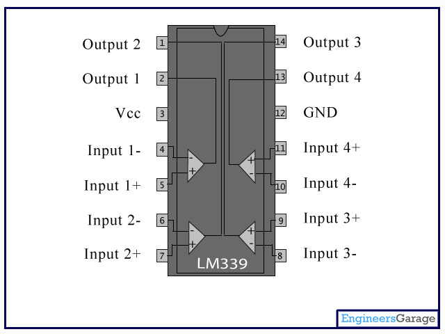 This is where the LM339 comes in. Let’s say that X-axis stays around 1.6v normally, and moves toward 0v when the joystick is moved left and 3.3v when the joystick is moved right. We connect this to Input 1-. We then use an exterior variable resistor to generate a voltage of 1v and connect it to Input 1+. The Output 1 pin on the LM339 is not currently connected to GND because the positive pin has a lower voltage than the negative pin. When we move the joystick left, we lower the voltage on Input -, and when the voltage drops below 1v, Output 1 switches to GND. If Output 1 is connected to a GPIO pin like shown in the GPIO tutorial, then the software can detect this and issue a keyboard command (such as KEY_LEFT). To get KEY_RIGHT, we will do something similar. We generate a voltage of about 2v and connect this to Input 2-, and we connect the same joystick output from Input 1- to Input 2+. When the joystick moves right, the voltage will increase to 2v and Output 2 will switch to GND.
The same process is then completed for the Y-axis using Inputs 3 and 4.
You now have working joystick input. It doesn’t give precision adjustment, but it’s still much better than the D-pad in many games.
[spacer height=”1px”]
I am trying to figure out if I can install this and use a different memory card with an OS on it and use the joystick as a mouse and configure the L & R buttons as mouse buttons. Do you thinks its possible?
Absolutely. The GPIO input can definitely be used to control the mouse. I wouldn’t be surprised if someone has written the code for it already. You’re welcome to post the question in the forum, since there could be someone out there with the code you need.
Can u please upload a circuit diagram or can u tell about the connection.
A diagram for the completed board I’m selling, or a schematic so you can make your own?
Any will be fine. I want to make it.
Hi, thanks for the tutorial! Could you send a schematic? I have a LM339 and would like to build it from scratch. I’m learning about electronics. Thanks in advance.
I’ll add schematics to the guides soon. All my focus is on getting Version 3 boards shipped. Look for updates in a few weeks.
I didnt understand how to attach an analog joystick.