
PSPi 6 – updated January 2025
January 2025
It’s been a busy year. I’ve shipped many, many boards, and it hasn’t left much time to make videos or post here much. I am now well-stocked on boards and components, so hopefully I can focus on more of the social stuff in the near future. Keep an eye on x.com and youtube for updates.
January 4, 2024
I’ve been shipping PSPi 6 boards in small batches for about a month. It’s going well, and I’m gradually scaling up production. I have a large batch in right now (available on backorder), and I’m shipping them as I inspect and solder components to them. I’m not announcing the availability everywhere just yet because I need to improve the soldering and testing process so I can ship faster. The backlog is about a week for orders with the Solder Avoidance Service and about 1-2 days for orders without it. I’ll update this post as availability changes.
October 9, 2023
August 20, 2023
July 21, 2023
May 23, 2023 Update
The Redesigned PSPi Compute
Back in 2021 when I released the PSPi Zero 5, I also shared my initial plan to create the PSPi Compute. The idea was for the Compute to mirror the features of the PSPi Zero, but to run with CM4 modules. Unfortunately, a shortage of ICs, CM4 connectors, and Raspberry Pi boards delayed the progress.
I recently went back to the work on it, and ordered a new prototype today.
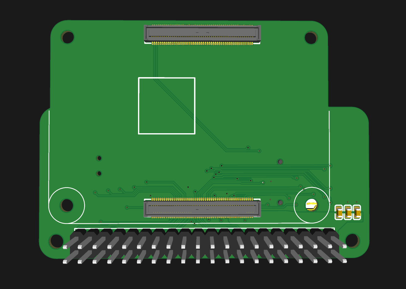
I’m walking back the original plan to make distinct boards for the PSPi Zero and PSPi Compute, and the goal is now to create a single universal board that works with every Raspberry Pi (40-pin and CM4). This board has a normal-looking 40-pin Raspberry Pi connector which it is compatible with all standard 40-pin Raspberry Pi boards, and a carrier board will interface the CM4 board to this 40-pin connector. This is designed for the Pi Zero and Zero 2, but will work with Raspberry Pi 3 and 4 boards, although they will not fit into the shell.
I’ve also flipped the mounting position of the 40-pin Raspberry Pi, making it compatible with pre-soldered Raspberry Pi Zero headers and eliminating the painstaking task of soldering and snipping header pins. While I can’t say yet that it will be an entirely solder-free assembly, I can say that any soldering required will be minimal.
There’s a long list of improvements and modifications I’ve made, which you can find detailed below.
The schematics/PCB files are hosted here. Please remember that these schematics probably still have issues.


Changes since PSPi Zero 5:
I’ve improved the board’s standby/sleep mode. It now cuts power to everything except the Raspberry Pi. The only limitation is putting the Pi itself into a low-power state, which, as far as I know, isn’t currently possible.
The microcontroller has been swapped out. I’ve switched from an atmega328p to an atmega8. This change reduces the cost by a dollar or two without removing any features.
I’ve improved the color depth of the LCD. It’s been upgraded from 18-bit to 21-bit DPI when using a Pi Zero and to 24-bit when using a CM4.
I’ve added pads for an extra joystick or two analog inputs.
The battery charger has been upgraded. I’ve swapped out the linear charger (TP4056) for a switching battery charger that is faster and more efficient.
The power circuit has undergone a significant redesign. This is such a substantial change that it will require its own section or video to fully explain. The end result is that the system can now run on USB power without a battery, and the power-off feature is more reliable when using high-current CM4 boards.
The left switch now connects to a GPIO, meaning it can be programmed to perform any function you desire.
I’ve added another LED on the left side. The top one still acts as the activity LED, and the bottom one can be programmed to turn on whenever you want.
Lastly (for now), I’ve fine-tuned the board shape. It now more closely matches the shape of the original PSP board.
Description
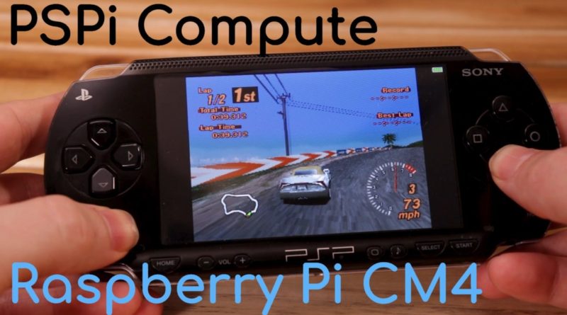
The PSPi is an interface board that replaces the motherboard in the original 1000-series Sony PSP. This board lets you use a Raspberry Pi as the brains, which means you can either turn it into an emulation system, or just run your favorite Linux distribution.
Features (will change as I prototype them):
Works with Raspberry Pi Zero, Zero 2, Compute Module 4 (with carrier) and PSP 1000 Series Case
The board has a 40-pin Raspberry Pi connector, and you can simply plug a Raspberry Pi Zero / Zero 2 into it. A normal Pi 3 or Pi 4 can also, be used, but you’ll probably need to use an extension cable or header.
With an add-in board, this is also compatible with every CM4 variant. Some have eMMC Flash while others use MicroSD cards. Some have WiFi, and some do not. The board has to work with all of them, which means it has to accept MicroSD cards on the Lite versions, and it has to allow USB flashing.
No PSP case modification is needed. The new board shape matches the PSP’s original one very closely, and doesn’t require any case modification.
Display
The LCD is driven directly by the GPIO pins in 21-bit and 24-bit DPI Mode 7
Works with the 800×480 LCD from Buydisplay.
The LCD backlight is dimmable and you can cycle through brightness levels by pressing the Display button. The lower the brightness, the more play time you get per charge.
Audio
Hardware volume control (VOL – and + buttons adjust volume, and the Sound button mutes and unmutes the amplifier)
Tweaked audio filter to remove most of the sub 1000Hz frequencies that the PSP speakers can’t produce
Separation between power and audio circuits, which eliminates noise in the speakers and headphones. The PWM audio is buffered, filtered, and amplified with low-noise linear regulators.
Power
Battery and Charging
The board has a standard JST PH connector for batteries. The battery charges using the round PSP charging connector (if wanted), or from the mini USB connector on top. The new charge IC uses a buck converter instead of a linear regulator, and is capable of charging the battery at 3A. I configured the IC to charge at a maximum of 1.35A because to keep the battery in good condition, and to keep board temperatures low.
5V Boost Converter for Pi
The Raspberry Pi boards all receive 5v from an efficient boost converter.
Battery Management
Instead of just monitoring the voltage and detecting whether the charger is plugged in, the microcontroller can constantly monitor power usage to provide accurate information about the battery status (see Input).
Battery Protection
The board has some basic reverse polarity protection in case your battery has a swapped pinout. The board is clearly marked + and – to prevent hooking the battery up in reverse. It’s always best not to stress-test these protection features.
The board will kill all power if the battery drains below 3.1v.
On/Off Control
The on/off circuit got a full redesign, and it now only supplies power to the microcontroller. The microcontroller then enables power to everything else in the system. It is more tolerant to quickly powering the system off and then back on. The previous version needed a few seconds to reset after poweroff, but this new one is able to power the board back on immediately after a shutdown completes. Functionally, this is identical to previous versions. A quick push of the power button will turn the system on, a quick push when the system is on will shut the system down and power it off, and a long hold of a few seconds will kill power to the board entirely regardless of whether the Pi has completed shutting down.
USB
USB Isolation
The miniUSB port is properly isolated from the battery . When the system is turned off, no battery power reaches the miniUSB port. Power is also unable to backfeed to the Raspberry Pi from a powered USB device.
USB Power
The miniUSB port powers USB devices directly from the battery when the system is powered on with a working Raspberry Pi, and it will range from 3.0v to 4.2v depending on the charge state of the battery. This power flows through an ideal diode, and experiences no loss in voltage.
If a USB device needs the full 5v (which may be unlikely, none of my USB devices needed 5v) or high amperage, the round charging cable can be plugged in, and the board will pass 5v directly to the miniUSB port, which will power the USB device regardless of whether the PSPi is off or on.
USB Charging
The miniUSB port is able to both provide and receive power. When using a USB device such as a thumb drive or keyboard, the PSPi will power the device using the battery (unless the round charger is plugged in, as stated previously). When a USB charger or other powered USB device is plugged in to the miniUSB port, the PSPi will begin receiving power and charging the battery.
Thermals
The CM4 uses a lot of power. Right now, I’m using a thermal pad to move the heat from the CM4 and into my board, and it seems to be adequate and eliminates the need for a cooling fan. There’s still some testing to do, but it looks promising.
Input
An atmega8 microcontroller handles all the input for buttons, joystick, and battery monitoring. The microcontroller is constantly calculating, storing, and transmitting button and analog statuses to the Raspberry Pi using I2C. The firmware can be updated using the FPC-10 connector.
The microcontroller has 6 ADCs in use. Two are used for the joystick, one for battery voltage detection, one for battery amperage detection, and two are available for anything you want to use them for. The joystick readings are sent directly to the Raspberry Pi, and the voltage and amperage calculations are done on the microcontroller before being sent to the Pi. The remaining pins are used for buttons, data transfer, and PWM output for the LCD brightness control.
The Raspberry Pi code is all written in C and runs more efficiently than the Python scripts used previously.
Prototype 1 – ordered February 1, 2021:
Rough proof of concept. I reused as much as I could from PSPi v4, just to see whether this project is doable with the CM4.
The ATMega328p microcontroller is up and running with very beta firmware. So far, I have the display, audio, buttons, joystick, and battery monitoring working, and I’m working out a few bugs with the I2C communication.
I’ve tested with an eMMC CM4, and I successfully flashed firmware over USB
The CM4 antenna connector is compatible with the internal antenna on the PSP case
I’ll probably film a video soon, and go over Prototype 1 thoroughly.
Prototype 2 – ordered February 21, 2021:
First test of DPI mode 7 (RGB888 reduced to RGB777 to save some pins)
Better PCB layout and pin usage
Includes connector for headphone/MicroSD board
Includes an expansion header for an Ethernet board (just testing this in case I use a non-wifi CM4, since every CM4 has gigabit ethernet)
Testing a new audio header that should be compatible with the original PSP speaker cable
Prototype 3 and 4 – ordered March 11, 2021:
Better circuit layout for the boost IC to reduce switching noise
New audio filter layout to decrease bass on the PSP speakers
Full Redesign Prototype 1 – ordered October 7, 2021:
Full redesign to include everything from the PSPi Zero and to substitute components that keep going out of stock
Switched to 2.1A synchronous buck charging IC instead of the 1A linear charging TP4056 to reduce the amount of heat generated during charging.
Switching from RGB777 to full 24-bit RBG888 for the display, giving the best quality possible.
This one is a major test of JLCPCB’s assembly capabilities
Full Redesign Prototype 2 – Ordered May 23, 2023:
Redesigned power circuit that fixes some problems that occurred due to the way the CM4 powers on and off.
Finished the basic design for the carrier board that interfaces with the CM4.
Flipped the Pi Zero connector so that pre-soldered headers will work with the board.
Super excited to see you working on a new version and sharing your progress. I know some pcb manufacturers support pcb assembly services even on low order counts, although likely with limited part availability. But you could potentially order boards with all the resistors, caps, and some support ICs pre soldered and then just have to source the more specialized connectors and other parts to hand solder later. Once you are finished with the design and publish it, I’ll probably do something like that to upgrade the PSPi version 4 I put together a while back. I don’t know if it’s reasonable to keep hoping for a new pi zero upgrade any more.
Oh man, I can not wait to see how this turns out. Hopefully into something a can buy.
Great project,
Nice to see a new version.
Oh cool, I am also very excited to see, that there is a chance to get a PSPi v5 :-)… my white PSP 1000 with a broken lcd is still waiting. I have no experience with soldering smd, so I would be very happy, if I could buy a fully assembled board. Many thanks for your great work. Many greetings from Germany, which is still in lockdown mode :-(…
Awesome news on the V5 I missed the prior versions would love to pickup a board when it’s done if you throw them up for sale!
Hello !!!!
Happy to see that you are back into business !
I have a lot of PSP laying around my garage 🙂
Today, you will find easily for sourcing a company that do full PCBAssembly for you (it may have some cost for certain parts) i can help you for this part if you want in the future…
Unfortunately, i think the CM4 consume much more power, not? Have you got an idea regarding the consumption?
Also, why don’t you keep the same screen with 480×272 resolution?
with the CM4, you still don’t have enough pins for a full RGB 888?
Have you think of using another design shell for all this extra power of the CM4? i mean, being able to have more buttons, and more space for a huge baterry (with the space of the PSP, i can’t on my side put more than 2700mA battery.)
Again, in term of look and design i will see something like the powkiddy s30 for instance :
https://www.aliexpress.com/item/1005002247569231.html?albpd=fr1005002247569231&acnt=248-630-5778&aff_platform=portals-tool&albpg=1161969894935&utm_medium=cpa&netw=u&dp=488e65056a7a257a7c22877c84ce2d03&albcp=10564357377&pvid=bc420fdc-3950-4cf6-a43f-1e3e7c5d4009&sk=_ePNSNV&scm=1007.23534.124000.0&trgt=1161969894935&terminal_id=d0d61455812d45649ca7cd156b5d1938&needSmbHouyi=false&utm_content=47843&albbt=Google_7_shopping&src=google&crea=fr1005002247569231&af=553779&utm_campaign=553779&aff_fcid=fe2c4f86b9be4ceaa38d4be08be30811-1619188954119-01141-_ePNSNV&gclid=Cj0KCQjw4ImEBhDFARIsAGOTMj-sSscVdKm6XummwPJ9cM38tPsTQfjaCRkZH10ocQgzYX3zZgrMrpYaAtoOEALw_wcB&cv=47843&albag=104632701295&aff_fsk=_ePNSNV&albch=shopping&mall_affr=pr3&albagn=888888&isSmbAutoCall=false&aff_trace_key=fe2c4f86b9be4ceaa38d4be08be30811-1619188954119-01141-_ePNSNV&rmsg=do_not_replacement&device=c&gclsrc=aw.ds&utm_source=admitad
Regards.
I’m working with a company that does assembly, and I’m trying to get these at least partially assembled.
Yea the CM4 uses a ton of power. It will probably get between 1-2 hours of play time depending on what you’re doing, and maybe 3 or 4 hours if I can tweak things a bit. The PSPi Compute board will be pin-compatible with the 480×272 screen from the last kit, as well as the new 800×480 screen.
The CM4 doesn’t have any more GPIOs than the Pi 4, and I’m using 2 GPIOs for audio and 2 for poweroff. I’m not ruling out RGB 888 yet, but right now I’m leaning heavily on going with RGB 777.
I also have a new Pi Zero PSPi board in the works.
Thank you for your reply!
I will be interested for the new Pi Zero PSPi board on my side… keep in touch! (if audio is included by default and the SD Card accessible on the side :-))
Regards.
Love your work,I love my psp street/E1000, so I would like to make a few requests:
Can you make compatible boards for the entire psp lineup, for example the psp street or psp go?
Is it possible to use this as a rasberry pi handheld, running linux on it? Are drivers needed for that, for communicating with the psp controls?
Not much except that, just hope this awesome project goes to the psp street too.
Also, is worldwide shipping possible, I live in South-East Asia, so that would be helpful, in regards to the kit I would have to buy.
The other PSPs are so different and lacking in usable space, that I’d say its unlikely that I’ll go beyond the normal 1000 series. I will make everything open source though, so you guys are welcome to adapt it for other cases.
The board will work with Raspbian, and the drivers should work with anything based off it.
Ok, so just to clarify, will it be compatible for lets say, Manjaro linux for raspi 4, and other distros? Also, what about the drivers, will they we needed, for navigating with the joystick in the psp, emulating a mouse, or can you/we be able to incorporate it into the input controller. I intend to use the psp as a handheld linux arm pc for everyday use, and this is a very appealing way for me.
BTW, you really need to advertise and spread this, as many psp fans will be interested, I myself found this by chance and am hooked up since.
Spread the word, and try hard on this, as we aim on helping you,in design,software, and I would very much like the psp to be breathed life into, both as a retro machine, and a linux handheld. Try making a final product, which will be available for commercial use. Love this project, and dream of having what is essentially a raspberry pi pc handheld psp linux amalgamation. Lol
I’m not familiar with Manjaro Linux, but the driver is written in c and interfaces with uinput and i2c, so it should work. The driver can probably be easily modified to work as a mouse. I’m a one-man show, so I am just focusing on getting the basic things working with Raspbian and Retropie.
The advertising will come as the board gets closer to completion. Many of the connectors and components for the PSPi Compute keep going out of stock before I can order them, and I don’t want to generate too much hype for something that might be delayed by out-of-stock components. The PSPi Zero board will ship very soon, and I’ll definitely promote it over the next few weeks.
And a few more questions,
Is there enough thermal headroom for the cm4 soc to have some space for stock thermals or “maybe” some overclocking, with the 3.5 Amp boost converter
With all the chopped off io, is it possible for you to replace the mini usb with micro usb, Or usb-c? It should be able to handle that, as mini usb is outdated and adopters for it are rare.
Thermals are going to be at their limits, so I’m unsure about overclocking headroom. I’m sticking with the stock miniUSB. USB-C is great, but the case would need difficult modification to make it fit. microUSB would probably fit, but its inferior to miniUSB in my opinion.
Well, Micro Usb is becoming outdated and ‘is’ weaker, but It is a bit hard to find adapters for the mini usb standard. Well, I can cope with that.
Is the cm4 running on stock speeds? Or has it been underclocked?
Ok, and what is the estimated time of completion, both for the pspi and pi zero projects?
I am interested in the adaptation of these boards for the psp street, suppose if the components are the same, both in the 1000 series psp and psp street, so will it be a matter of adapting the board for the psp 1000, alongside with all the components, to fit inside the psp street, with little to no changes in the electrical components of the board. Please clarify whether I am right or wrong.
Sorry for the torrent of comments, just interested
Hello, as part of my plans for the modifying of this board for the psp street, I found dual analog sticks to be possible of the psp. This might prove very useful in Raspbian (rasberry pi os, why even?) and such, as controls are limited in the psp buttons. So, can you share some details on pins used for the analog stick ,and any spare gpio pins available, if I want to hack another stick onto the psp. Thanks.
Hi,
thanks for the great project. I currently use the Zero Version (5), but noticed, that the Pi Zero is to weak for PSP-Emulation.
So I am looking forward to the compute version.
Will it be possible to just replace the Zero-Mainboard with the compute Mainboard and use all the other Hardware (JST 2.0 Akku, 800×480 Display), or should I better use another PSP with new Stuff?
And Do you think, it would be better to use a compute module light with sdcard, or should there be used a version with emmc and just use an sdcard for additional storage (then I would think about an 8 GB Version for the OS and 64 GB sdcard for storing the roms).
And I am struggling with the RAM. Since I want to emulate Things like Gameboy, SNES, N64 (which the Zero version do well) AND PSP, I don’t know, if 2 GB RAM are enough or if I should go higher. Do you have a suggestion for me on this?
Yes, the Compute board will work with the LCD and battery from the PSPi Zero.
I’m making this board so that it is compatible with every variation of Compute Module, but I believe the recommendation will be the Lite one once I have everything finished. I think I can get full 24-bit display output with stereo audio on the Lite, and then use mono audio on the emmc versions. I’m still prototyping and testing things though, so none of this is set in stone. I have the 5th prototype in my hands now, and I’m trying to work out some bugs. It’s very expensive to make these prototypes, so I have to thoroughly test things before purchasing the next one.
As far as RAM, I’m not sure. I’ve seen some people recommend the 4gb version and higher for emulation, but I don’t know enough about the reason for the recommendation.
Is it possible could you tell us what parts of the psp original part are needed to be kept or be acquired because maybe brought separately to make a easier purchase
Pretty much everything in the original PSP 1000 is needed, except for the motherboard and LCD. You’ll need my board, an LCD, and a battery to complete the build. I’ll post more info over the next couple weeks, detailing and linking to everything that’s needed.
Hello!
Very nice project! I have a PSP which, unfortunately, I don’t use since a very long time. Maybe this project will give it a second life!
I am a professional electronics engineer and I have some (small) suggestions regarding your design. First of all, very impressive that you got everything working as a “discrete” implementation with lots of MOSFETs. If it’s working and you are happy with it, no need to change. Maybe this is the cheapest way to do it.
I would most probably use a power mux with priority switchover like the TPS2116. Viewer components, less space, lower quiescent current (?) than your ideal diode implementation.
I would maybe also use an on/off push-button controller like the STM6600. They have some features which could be useful for your design, e.g. monitoring the battery voltage and not allowing turn-on if it is too low. Unfortunately sometimes they are quite expensive for what they are.
For the audio amp I really don’t think that you need the additional LDOs. I would just supply the amp via the 5V of the boost converter. The amplifier has a quite high PSRR and I don’t expect that you can hear a difference if you just use V_5V0 for the supply of the amp. When in doubt you could us a pi filter for the supply of the amp with relatively large decoupling caps. Also, you save some micro-amps when you disable the LDOs compared to the shut-down of the amp (mute) but you also burn a lot of power with the LDOs if not muted.
I come from an industrial environment and I would probably add additional ESD protection diodes for the push buttons. Maybe not necessary here but also not very expensive.
For connecting USB I would maybe try to design a custom Flex-PCB with USB connector to connect the two boards.
Regarding the PCB layout I usually suggest to switch from a 2-layer board to a 4-layer board for medium complex designs. The additional price for 4-layer boards is is very small but the layout usually improves quite dramatically in power- and signal-integrity. The two inner layers should be reserved as much as possible for power and ground, the two outer layers for signal routing.
Greetings
Stefan
Thank you Stefan. I’ll spend some time looking over your suggestions.
Hi, I’m such a fan of your pspi project and have been following it for years!
With the latest revision and it’s inclusion of a CM4 daughter board I was excited to see if I can mod my psp with your project.
I was wondering if you had any advice on how to go about ordering a prototype board, would it be as simple as sending off the board schematics and BOM list to a manufacturer/assembler like PCBWay or would there be more too it?
It will be pretty simple (but expensive) to order them from JLCPCB. I plan to discuss this some and show the ordering process in my next video.
Super awesome project 🙂 I had a PSP-1000 when it was new. I no longer have it, but it was one of my most prized possessions as a child, so I’m definitely interested in making a retro PSPi
Hopefully they announce a CM5 to further expand the possibilities of this project. I’d love to buy a kit to assemble one 🙂
This is such an exciting project. I keep finding my retroid pocket is so uncomfortable to hold vs my psp. Also would be curious about using the banana pi cm4 which features newer generation cores at a higher clock speed https://www.banana-pi.org/en/core-board-and-kit/129.html
It will require a special carrier board, but yes, I’m going to try to get it working in this.
I love to read posts like this which are informational.
How do I get my hands on a board?