
Notifications
Clear all
Topic starter
January 10, 2017 11:02 pm
I can't wait for this. I have the PSP, ordered the 100.2.1 Kit, have the Raspberry pi zero 1.3 kit, and ordered the screen. Anything else required?
To prep for the soldering work, I have been practicing on a "Learn to Solder" kit from Fry's. Will make sure to update this as the project progresses.

January 10, 2017 11:30 pm
Sounds like you have it all. Was a microSD card and SD to microSD adapter included in the Pi Zero kit?
Topic starter
January 10, 2017 11:43 pm
Yes, 8 Gig Card and adapter. Will swap it for a 32. What is it using for software? Can I pull retropie ?
Topic starter
January 11, 2017 4:41 am
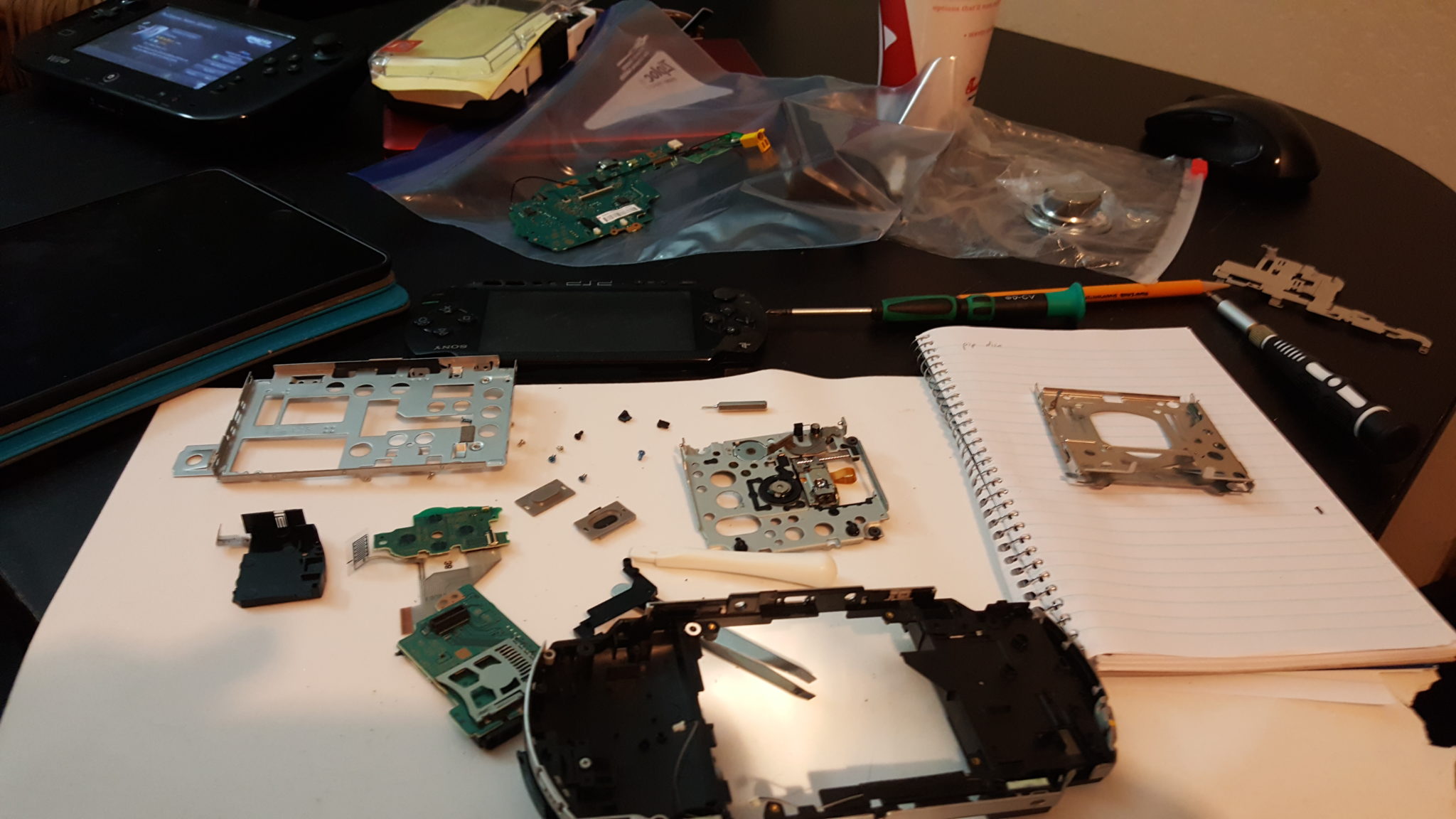
Still have about a week before the lid and kit come in but wanted to make some progress. Went ahead and did the PSP tear down. Looks like someone else has been in here and forgot some of the screws. A good amount were missing. I used this tutorial as well as this one ( https://www.ifixit.com/Teardown/PSP+1000+Teardown/1234) and got it apart. Did have a snag on the back panel and chipped out some of the black plastic. Will keep an eye online for a replacement. Everything else came out smooth.
Topic starter
January 16, 2017 7:07 am


Topic starter
January 16, 2017 7:11 am
Called it a night. Tomorrow going to borrow a friendsmall multimeter to make sure power is up correctly. Then I'll do the SD. I checked the dpad fit and appears the SD reader went slanted so I sandpapered the bottom lip and mow.fits perfectly.I know the soldering is bad but not to bad for someone who has never soldered prior to 2 weeks ago. Hope the screen comes in. I am anxious to continue.
January 17, 2017 3:49 am
Waiting on the same LCD on Jan 4. I've ordered everything I need, and the LCD is the only thing that wasn't provided with a tracking number. I'll keep ya posted when mine arrives.
January 17, 2017 4:26 am
If you ordered the one I linked to, they usually take about 3 weeks.
Topic starter
January 17, 2017 6:59 am
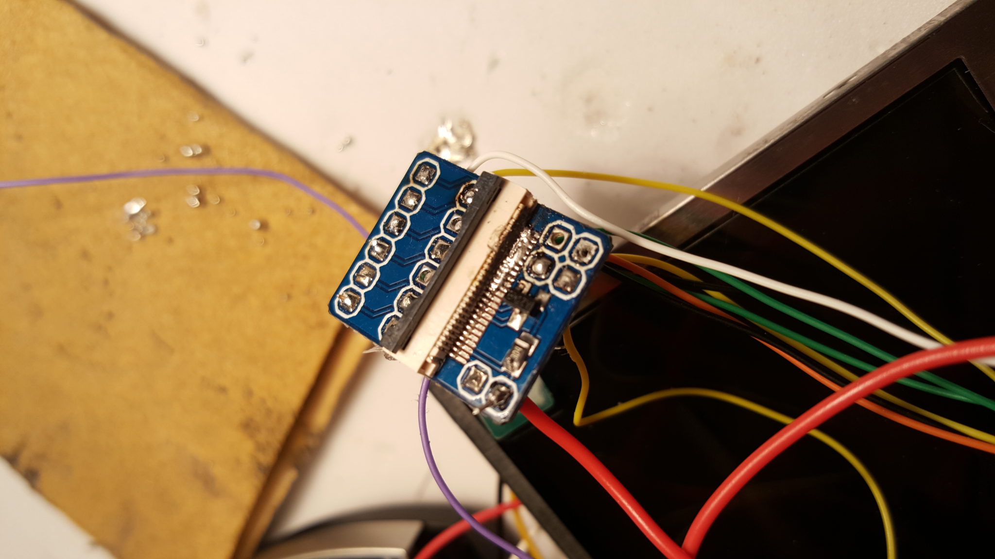
Awesome. I reached out to the company, they said 15 to 35 days. Hopefully closer to 15 ;). Today I got the right side and left side controls wired up. On the right side, I couldn't quite make out the ones the video had used (fpc 24). I ended up doing o, x, square, triangle, start select, one switch, volume up and down, and right trigger. Is the orange and green the lcd lines coming off the power?
January 17, 2017 1:29 pm

Hope this helps. The blue circled connections go to any available green GPIO pin other than 13 and 18, since they are used for audio.
Topic starter
January 18, 2017 6:48 pm
This will help a ton! I got the AMP wired up as well as the FPCs. My rookie soldering skills did cause a problem on the SD card. The plastic melted a bit so had the 1 & 2 pin touching. (Verified with multimeter) I cleaned it up best I could but had some more melting :(. Having already glued the SD Card in, it would be a chore to replace it. I am set to buy the v3 once it comes in so will just move forward with this and give it a shot. Finger crossed.
January 18, 2017 7:00 pm
Yeah the most important thing is to make sure no other pads are touching. That would ruin your day. A blow drier or heat gun might soften the hot glue enough to remove the adapter if you decide to.
Or, you can always just install the microSD card directly into the Pi Zero if you think the adapter is toast. It won't be as easy to remove, but hey, it will work.
January 26, 2017 5:42 am
Ok, I ordered my LCD (same one from the link) on Jan 4th and it arrived yesterday, Jan 25th. All of the small parts I've ordered have been about 1 1/2 weeks. The larger stuff (ie. case) has been about 3 weeks. (All items shipped from China).
Topic starter
January 26, 2017 4:48 pm
Sweet!! I keep checking the mail everyday for it! Side note is there any update on video part 2? Even if unedited, it helped a lot.

January 27, 2017 12:37 pm
It appears they did a redesign on the board. I have 4 on the way, so I'll be dealing with this too. I can't quite make out the lettering on the two chips, so is there any way you can either get a closer pic of them or tell me what they say?
Have you tried hooking it up to see whether it works without removing the regulator. If it works, then the board will run a little less efficiently.


January 27, 2017 3:55 pm
Ok I did some research. It's the JW5022. I'm a little surprised by this one. It's really good and super efficient. You might not need to remove it. It really just depends on how much of a voltage drop the component creates.
http://wenku.baidu.com/view/7242e146b9f3f90f76c61bd0.html
Topic starter
January 27, 2017 4:40 pm
Awesome. I'll wire it up as is and see. Thanks again.
January 27, 2017 6:49 pm
I'll be starting mine on Sunday. Let you know what I see when I tear it apart.
Topic starter
January 28, 2017 4:57 am
You may beat me to it. PAX South is this weekend so will be attending that.
Topic starter
January 28, 2017 7:44 pm
Was wiring everything up and realized that I didn't have a power switch. What are people using? What was used in the video? (Store or Amazon link?)
January 28, 2017 8:52 pm
We're using the original switch that's on the PSP's right control board.
Topic starter
January 28, 2017 10:12 pm
Ok. So made a boo-boo on the fpc24. Drop some soldering in it and couldn't clean it out. 😣. I ordered another and did some small stuff in the mean time. Got the batteries knocked out, and followed the wiring diagram for the power and ground on the boards. I also wired up the SD to the pi. I did have the wires super long on everything so was trimming down.


January 28, 2017 10:18 pm
I've made some changes to the new version of the FPC-24, so you can more easily solder to the pads on the bottom instead of using the holes. Might help prevent issues like this in the future.
Topic starter
January 28, 2017 10:24 pm
**tip**
Get familair with tinning the soldering tip. Being one that is not familiar with soldering, I just jumped into this but am learning how much easier it is. Still haven't got it down 100% but do take the time and look it up if you'really new to soldering. Save your selves the melted parts/wires and burnt fingers 🙂
January 28, 2017 10:26 pm
A wet sponge for the soldering iron tip helps a ton
January 28, 2017 11:51 pm
Steel sponge works well also.

Topic starter
January 31, 2017 6:18 am
Ok new fpc came in. Love the new design. Made it so much easier. Also grabbed some solder and new tips for my iron. Tinned the tip and went to work. Wired up the new fpc24 and made sure power/grounds were good according to the image. Then did a quick test fit. Everything is lining up closely. I can see the light at the end of the tunnel! The lDC sits tight but I think it'll work. Anyone have any suggestions to the GPIO layout? A diagram would be really useful to us noobs. Going to hit the Google.


January 31, 2017 2:21 pm
I don't have a diagram because I use different GPIO pins on every build. Most of the GPIO pins function the same, so I just use whatever pins are easiest and tweak the software once I'm done soldering so it looks for the commands on the right pin.
Topic starter
February 1, 2017 8:49 am
SO put some time on this. No luck though. Screen wouldn't kick on and or pi power up. Did some tests and looks like no power was leaving the LED so I pulled it out. Still nada. I then went ahead and wired the screen up to the pi and plugged it into the wall outlet. Pi fires up but screen still dead. Multimeter confirms 5V going into it.
Topic starter
February 1, 2017 8:57 am
Alos forgive the noob questions
So I popped out the multimeter to see whats going on. I have 5.07 coming off the charger and going into the power module. However all hot lines leaving it are only at .47. I wonder if I set this up properly.
February 1, 2017 12:36 pm
Alright you've got a couple different things going on. The module should be outputting 5.0-5.1v, so you might have a short somewhere. Let's isolate that from everything for a bit. Do you get any indication lights on the module when it's being charged or when you attempt to draw power from it?
I'm curious about this LCD. When testing it, did you have it powered by the same 5v power source that was powering the Pi? A picture would help me a lot. I bought some new software for the forum, so it should be much easier to upload and display images now.
Topic starter
February 1, 2017 2:33 pm
I don't have the batteries wired in yet. Just wanted to make sure that's called out. Ok I do get a red light on the module. I wired up the power button and get a brief blue when clicking it on. For the lcd, I originally had a red 5+ coming off the amp. On first pass with nothing working, I popped it off. When I plugged the pi power in and noticed 5v, I then wired it directly to the pi (p1 and p6 I believe) with the v1 yellow going to TV. With this setup I checked power and verified 5v going into the lcd but no turn on. The pi is on cause I see the green light come on and stay.
I keep getting "Error - internal server error" when attempting to load pics
February 1, 2017 2:51 pm
Ok, yea the batteries need to be wired up before this module will work correctly (it might work somewhat, but not reliably). The module will have a steady blue light when it's powering something.
Also, if you have the on/off board wired between the module and the Pi, and you're pressing the button to turn it on, it will only power on for a second or two if the on/off board's TX pin is not connected to a positive voltage.
As far as the LCD...if you're using the same 5v and GND from the Pi's pads (and you have the polarity right), then the buck converter is probably to blame. I'll do some research.
Topic starter
February 1, 2017 3:11 pm
Got ya. When I get home I am thinking to do a tear down and then rebuild. Pretty sure I can clean it up alot now that I have an idea what to expect.
February 1, 2017 7:53 pm
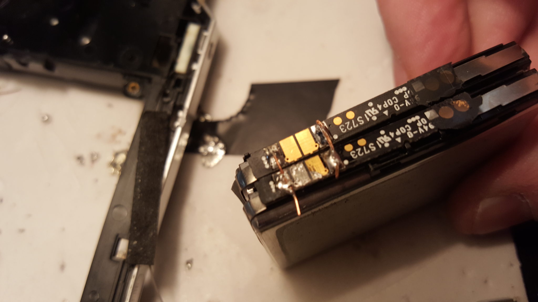
Pulled the back off of the LCD I ordered. Completely different. I did use the link that you have on your store page, so I'm guessing you will have the same look when your parts arrive.
The Yellow one is JW5022S
The Pink one is 25C4006E M1I-12G
February 1, 2017 7:59 pm
Pulled the back off of the LCD I ordered. Completely different. I did use the link that you have on your store page, so I'm guessing you will have the same look when your parts arrive.
The Yellow one is JW5022S
The Pink one is 25C4006E M1I-12G
Ok so both of you got the same one. I ordered a bunch of them, so yea I assume I'll be getting the same. Have you tried powering it off 5v yet?
February 1, 2017 8:28 pm
Not yet. If not tomorrow, I will this weekend.
I did notice the same regulator, but the boards that Allen and I ordered were different. Thought that was odd.
Topic starter
February 1, 2017 9:30 pm
I'll give it a shot tonight. So to be clear. I pop out the JW5022 buck converter and run a 5v+ into Pin 2 (VIN 2 - http://wenku.baidu.com/view/7242e146b9f3f90f76c61bd0.html - the one immediately under the little circle on the the top). Just being careful, don't want the month wait if I bork it.
February 1, 2017 9:43 pm
I'll give it a shot tonight. So to be clear. I pop out the JW5022 buck converter and run a 5v+ into Pin 2 (VIN 2 - http://wenku.baidu.com/view/7242e146b9f3f90f76c61bd0.html - the one immediately under the little circle on the the top). Just being careful, don't want the month wait if I bork it.
If you hang tight for an hour or two I'll figure out this schematic and let ya know. It might be simpler than that. I'm also trying to verify that it's bucking to 5v and not 3.3v.
Topic starter
February 1, 2017 10:02 pm
No worries, I still got a few hrs at work. Went ahead and ordered the new power module, I think I might have messed it up popping off the clips. I am going to borrow the fiancee's hair dryer and pull it apart tonight and see if there is anything I missed or did wrong.
February 1, 2017 10:17 pm
This is what I'm gathering so far. I drew lines to show the path of the power. I'm still making the assumption that it's dropping to 5v, not 3v.
It doesn't actually drop to 5v until after the inductor (the component labeled 101 that sits above the 8-pin chip) during normal use. If I had one of these in my hand, I would hook 12v to it so I could see normal operation and verify voltages.
If it is indeed dropping to 5v, then it appears that Pin 3 is the pin to hook to. You can also attach after the inductor and to the component with the 0 on it. I'm still not 100% sure on this, maybe 90%
Topic starter
February 1, 2017 11:02 pm
"component with the 0" the 220 vt one?
February 1, 2017 11:16 pm
Yep. At the end of the red line I drew. That whole thick trace appears to be a good connection point. If either of you guys has a 12v power source you can test the LCD with, it would tell us for sure whether it reduces to 5v.
If you do try the 12v, then you have to connect a ground wire from the Pi to the GND on the LCD controller. If you don't, then the composite video won't work.
Topic starter
February 2, 2017 4:48 am
I think I know why the power module is not working. Looks.like like a short like you said. I went ahead and ordered the new one. The hair dryer worked really well taking it all apart 😉
Topic starter
February 2, 2017 8:25 am
Calling it a night. No go on this screen. I wired a hot wire to Pin 2 and then tried 3. At 2 I get 0 going past that. On pin 3 I read 5v out to the fpc (can't find anything in the plastic past that) but no power up on the screen . did alot of Googleing and no dice. Once someone gets one and confirms it is useable, I'll order one of those.
February 2, 2017 1:05 pm
Calling it a night. No go on this screen. I wired a hot wire to Pin 2 and then tried 3. At 2 I get 0 going past that. On pin 3 I read 5v out to the fpc (can't find anything in the plastic past that) but no power up on the screen . did alot of Googleing and no dice. Once someone gets one and confirms it is useable, I'll order one of those.
This is why I can't stock LCDs. Every order surprises me with something different. I've got a bunch of these arriving any day now, and I expect to get the same thing. Once I get it and remove some components I'll probably be able to find a solution.
On the power module, have you tried cleaning up the solder and soldering up the battery and power inputs to see whether you get anything? These are pretty resilient.
Topic starter
February 2, 2017 2:44 pm
Tried to clean it. No luck. Going to grab some wick from Frys tonight and give it abother shot.
February 2, 2017 3:52 pm
Did some continuity checks, and I agree with your drawing.
Removing the buck and jumper pin 2 > pin 3 looks correct.
Working on this right now, will post pictures when completed.
February 2, 2017 3:59 pm
Did some continuity checks, and I agree with your drawing.
Removing the buck and jumper pin 2 > pin 3 looks correct.
Working on this right now, will post pictures when completed.
Any chance you can try 12v on the power input first?
February 2, 2017 4:26 pm
Did not try.
Removed the buck and there is continuity from pin 2/3 to the resistor.
Will hook up to 5V after lunch to verify.
February 2, 2017 4:31 pm
Did not try.
Removed the buck and there is continuity from pin 2/3 to the resistor.
Will hook up to 5V after lunch to verify.
That's some good looking work. I asked about testing it first because I can't be 100% sure it's dropping to 5v. It should be 5v, because there is a second buck converter up top that should be knocking it down to 3.3v.
February 2, 2017 5:18 pm
Thanks, helps to have the right tools. Should've used wire to bridge it, but solder works too.
OK...so... Setting my power supply at 5V resulted in 4.2V at the resistor. To get 5V at the resistor, I set the power supply at 5.75V.
February 2, 2017 5:25 pm
You might be getting a voltage drop across the inductor. Whats the voltage at the pin2/3 bridge?
February 2, 2017 7:38 pm
There was a 0.7V drop across the diode.
I removed the diode, bridged it, and I now have 5V from the input to the resistor.
Not having the diode shouldn't be an issue. But I know it's there for a reason...
February 2, 2017 7:44 pm
It's probably a leftover from a previous version of the board. Most of the cheap buck converters use a diode in their function. This buck doesn't need it, so I can't tell you why they left it. On a related note, there is also a capacitor and inductor on the input of the chip that don't appear to be doing anything.
February 2, 2017 7:51 pm
Thanks for the help.
I'll get a good start on this Saturday.
Topic starter
February 2, 2017 9:23 pm
Cool. let me know how it comes out. If all else fails I saw Fry's has 4.3" LCD back up cams so could grab one of those and give it shot.
February 4, 2017 7:00 pm
Started my project, but ran into a roadblock. Need to order a new audio jack. The teardown PSP I was using, the audio was crackling. So, I ordered a new part. Will start again later in the week (hopefully by Thursday). But, so far so good.
Question for anyone ... when I tore down the PSP I had, I couldn't find this... http://www.ebay.com/itm/Original-Joystick-Rubber-Contact-Button-Replacement-Parts-For-PSP-1000-Fat-/262278863185?hash=item3d1109d951:g:lSQAAMXQDrJRzA2h
Anyone have any idea? Or a picture where it would be located?
Topic starter
February 5, 2017 7:22 am
got another screen. Doesn't appear to be plug and play. Which converter gets pulled?
February 5, 2017 1:56 pm
got another screen. Doesn't appear to be plug and play. Which converter gets pulled?
I think your image got deleted. I'm not seeing it.
Started my project, but ran into a roadblock. Need to order a new audio jack. The teardown PSP I was using, the audio was crackling. So, I ordered a new part. Will start again later in the week (hopefully by Thursday). But, so far so good.
Question for anyone ... when I tore down the PSP I had, I couldn't find this... http://www.ebay.com/itm/Original-Joystick-Rubber-Contact-Button-Replacement-Parts-For-PSP-1000-Fat-/262278863185?hash=item3d1109d951:g:lSQAAMXQDrJRzA2h
Anyone have any idea? Or a picture where it would be located?
That's the conductive pad for the joystick and sits in the left piece on the LCD bracket. It's not really needed on these mods.
Topic starter
February 5, 2017 3:39 pm
February 5, 2017 7:24 pm
Buddy you can't catch a break on the LCDs. I just received a huge order of LCD (not from eBay, I'm still waiting on those) and I received this exact one.
So here's the problem...the buck converter on these doesn't drop the voltage to 5v, it drops it directly to 3.3v. If you remove the components and hook 5v to it then you will fry everything. I'm working on a solution and Ill post it soon.
To everyone else receiving new boards...please find a way to attach 12v to them and measure the voltages coming out of the 8-pin buck converters. If these new designs have the voltage dropping to 3.3v immediately, then you will destroy your board when you attach 5v directly to the pins.
February 5, 2017 8:34 pm
So I removed everything that's not needed anymore, except for the capacitor labeled 220. It's not needed, but an extra capacitor never hurts.
That is there the 3.3v gets attached. Where is the 3.3v coming from you ask? This little guy.
February 6, 2017 5:04 pm
Started my project, but ran into a roadblock. Need to order a new audio jack. The teardown PSP I was using, the audio was crackling. So, I ordered a new part. Will start again later in the week (hopefully by Thursday). But, so far so good.
Question for anyone ... when I tore down the PSP I had, I couldn't find this... http://www.ebay.com/itm/Original-Joystick-Rubber-Contact-Button-Replacement-Parts-For-PSP-1000-Fat-/262278863185?hash=item3d1109d951:g:lSQAAMXQDrJRzA2h
Anyone have any idea? Or a picture where it would be located?
That's the conductive pad for the joystick and sits in the left piece on the LCD bracket. It's not really needed on these mods.
Thanks!
February 6, 2017 5:06 pm
It's probably a leftover from a previous version of the board. Most of the cheap buck converters use a diode in their function. This buck doesn't need it, so I can't tell you why they left it. On a related note, there is also a capacitor and inductor on the input of the chip that don't appear to be doing anything.
I'll leave the capacitor. You suggest removing the inductor? Thinking it won't make a difference.
February 12, 2017 6:56 pm
Making some progress...
Adam, I seem to have lost this :
Mini Switch (the same as the original PSP Wifi switch) for switching the audio on and off (optional feature)
I don't see anywhere in your store to order another one. Is it possible to order one from you?
April 1, 2017 9:23 pm
I just discover that this "clone" converter module take the 12v and drop it directly to 3.3v. Ill put some closeup pictures and more detail about the voltage of this step down converter jw5022s.
April 1, 2017 9:28 pm
It will, but the diode M7 will cause so much voltage drop that the LCD will either flicker or not work at all. That chip needs over 4.75v to work, and the diode will drop the voltage just below that.
Removing the diode would get you up and running.
April 1, 2017 11:11 pm
While probing the voltage i short some pins and nothing make sense anymore so i burnt the jw5022s... but ive been able to make a little schematic of is pin. Picture below.
- Pin#1 nc
- Pin#2 Vin
- Pin#3 Vout
- Pin#4 Gn
- Pin#5 Gn with resistor 8.2kohm
- Pin#6 to Ground not connect
- Pin#7 Vin with resistor 99.3 kohm
- Pin#8 Gn with capacitor* (look like cause there is no resistance but only miloamp going down)