
PSPi 1000 Version 3
9/9/17 Update
Guys, I’m officially calling Version 3 complete after this weekend and my focus will be entirely on Version 4. Before that happens though there’s one last thing to do. I want to make sure everyone is happy with what they received. I shipped many of these V3 boards, and only a few people posted in the forum or contacted me about issues they had. Most of the issues were related to the soldering process (which was a little difficult in V3), some of them were simple software glitches. I even replaced a few boards because they arrived DOA. So, before moving on I’d like to hear from anyone that isn’t satisfied with their board. I only built these because you guys asked, so this is only worthwhile if you’re happy with what you purchased. Use the contact page if needed. You can also use the forum or contact me on Discord.
Thank you for following my work.
Visit the Store page to order
This build takes the PSPi into new territory. This majority of the time spent on this build wasn’t with a soldering iron, it was with schematic and PCB design. It started as a rat’s nest of wires in Version 2 and grew into the modular Version 2.1, and has grown again into a full all-in-one at the request of you guys reading this. Many of you wanted something you could build in an afternoon, so I’d like to introduce the Version 3. It does everything that the previous versions did and includes a few new features that weren’t ready when those versions were made.
Features:
Battery management
- Properly charges the 3.7v lipo batteries. Battery voltage ranges from 3.0v (fully discharged) to 4.2v (fully charged) The board has components that prevent the battery from overcharging, overdischarging, and short-circuiting.
- The green LED is lit when the battery is operating at normal voltage. The LED becomes orange when the battery drops to about 3.5v. At this voltage only about 10% of the battery capacity remains. This warning voltage is adjustable, and can be changed by turning the potentiometer in the center of the board.
- When the system is plugged in for charging, the LED will turn orange while the battery charges. This happens when it is powered on or powered off. If the system is powered off, then the LED will turn green when the battery has fully charged.
- If the battery drops below 3.0v the system will fully power off and will not function until the battery is recharged.
Soft On/Off
- A quick push of the power switch turns the system on. Once on, it requires a connection to the Raspberry Pi to stay on. If the Raspberry Pi doesn’t have an SD card installed or if it doesn’t have the correct config.txt, then the system will not stay powered on.
- Once the operating system has booted, a quick push of the power switch will send a signal to the Raspberry Pi and the system will fully shut down. Once shut down, the system will fully power off. It will power on again when the power switch is pushed.
- If the system is not operating properly, the power switch can also be used to force the system to power off. Holding the switch in the pushed position for about three seconds will fully kill power to the board. It will power on again when the power switch is pushed.
Audio
- PWM audio amplification is included, and includes audio filtering for better quality sound.
- The switch on the left side of the board (in the position of the original PSP’s WiFi switch) will turn the audio fully on and off. Up position turns audio on, down position turns audio off.
USB data connection
- The miniUSB at the top of the boards connects to the USB port on the Raspberry Pi. This allows USB devices (thumb drive, keyboard, etc.) to be connected. This is not meant for high-power devices such as hard drives. If you need high-amperage, use a powered USB hub.
Simple Joystick
- Connects to the PSP’s joystick, allowing for up/down/left/right control. This joystick doesn’t allow for precision control, but it does allow for in-game movement in the same manner as the d-pad. This uses the same GPIO pins as the d-pad.
Hardware Installation Guide
Please test your Raspberry Pi Zero (or Zero W) fully before spending time soldering it to this board. I’m making some changes to the guide to provide some testing before the assembly begins. For issues, see the Common Problems section at the bottom of the page.

Start with a disassembled PSP. You’re going to need some of the old parts.
[spacer height=”1px”]
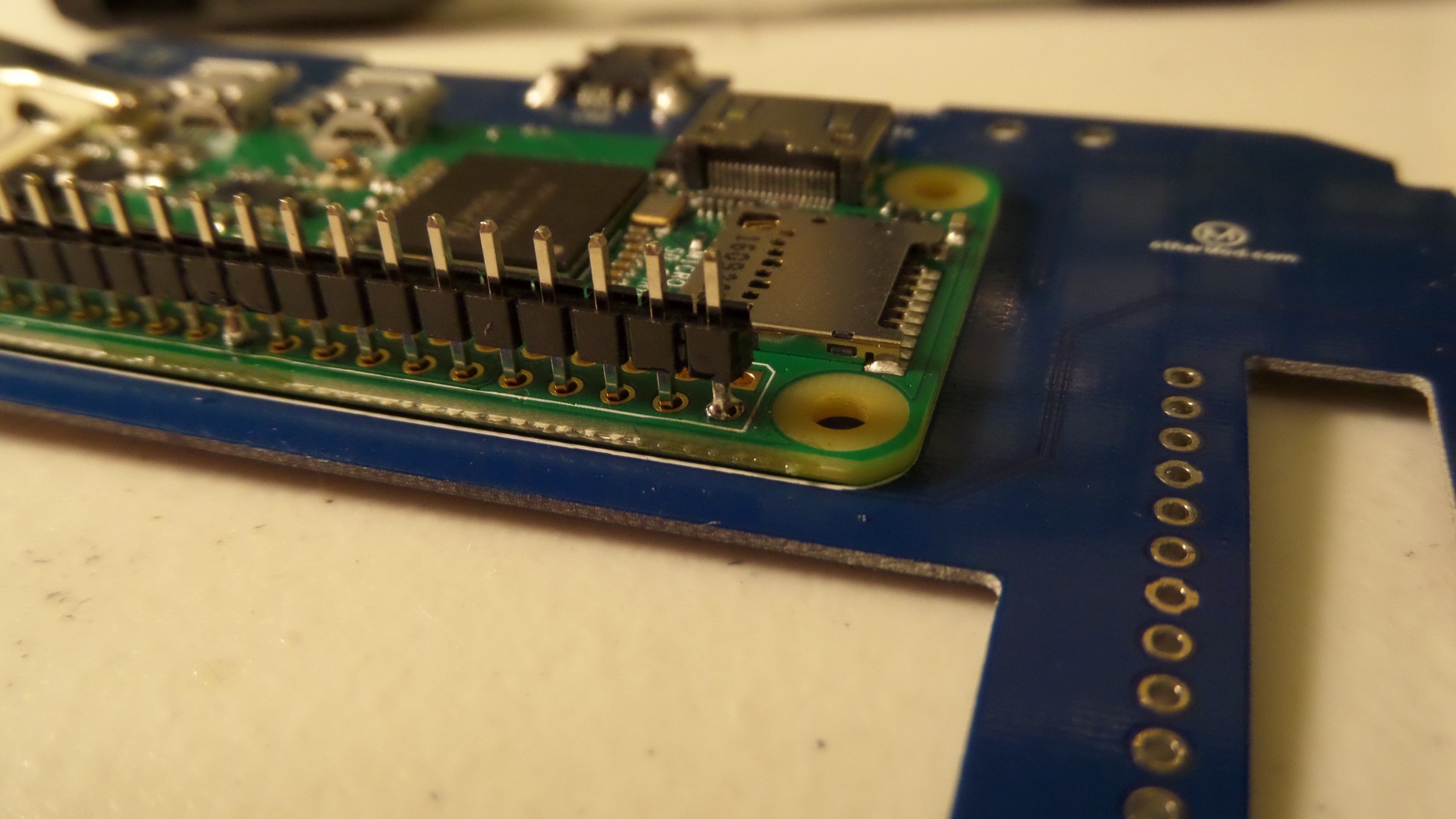
Attaching the Pi to the Board

Here’s how the Pi Zero gets installed onto the bottom of the board.
[spacer height=”1px”]

Secure it with clamps. Make sure the holes line up. It’s time to solder them together.
[spacer height=”1px”]

Some of you may be able to solder the boards together without these pins, but they do make the whole process easier.
Use something to prop the board so you can keep the pin protrusion small. Make sure they are only barely above the board, otherwise they will short out on the LCD bracket.[spacer height=”1px”]

Start soldering the pins. So typically I only use lead-free solder and it usually works fine, but I don’t recommend it here. It just doesn’t do the job well enough when large boards like these are pulling the heat from your soldering iron. Please use safe practices when soldering with lead. Rosin flux also makes the process a lot easier.[spacer height=”1px”]

[spacer height=”1px”]

Once you’ve soldered the top side, do the same on the bottom side. You can use clamps again to make sure the boards are pulled together.
[spacer height=”1px”]
Solder a couple to keep it all together, then start cutting off the excess pins using flush cutters.
[spacer height=”1px”]

Cut them as low as you can, but leave enough to solder to.
[spacer height=”1px”]

Half of the pins are soldered. You can see the shiny rosin flux I used to make the process easier.
[spacer height=”1px”]
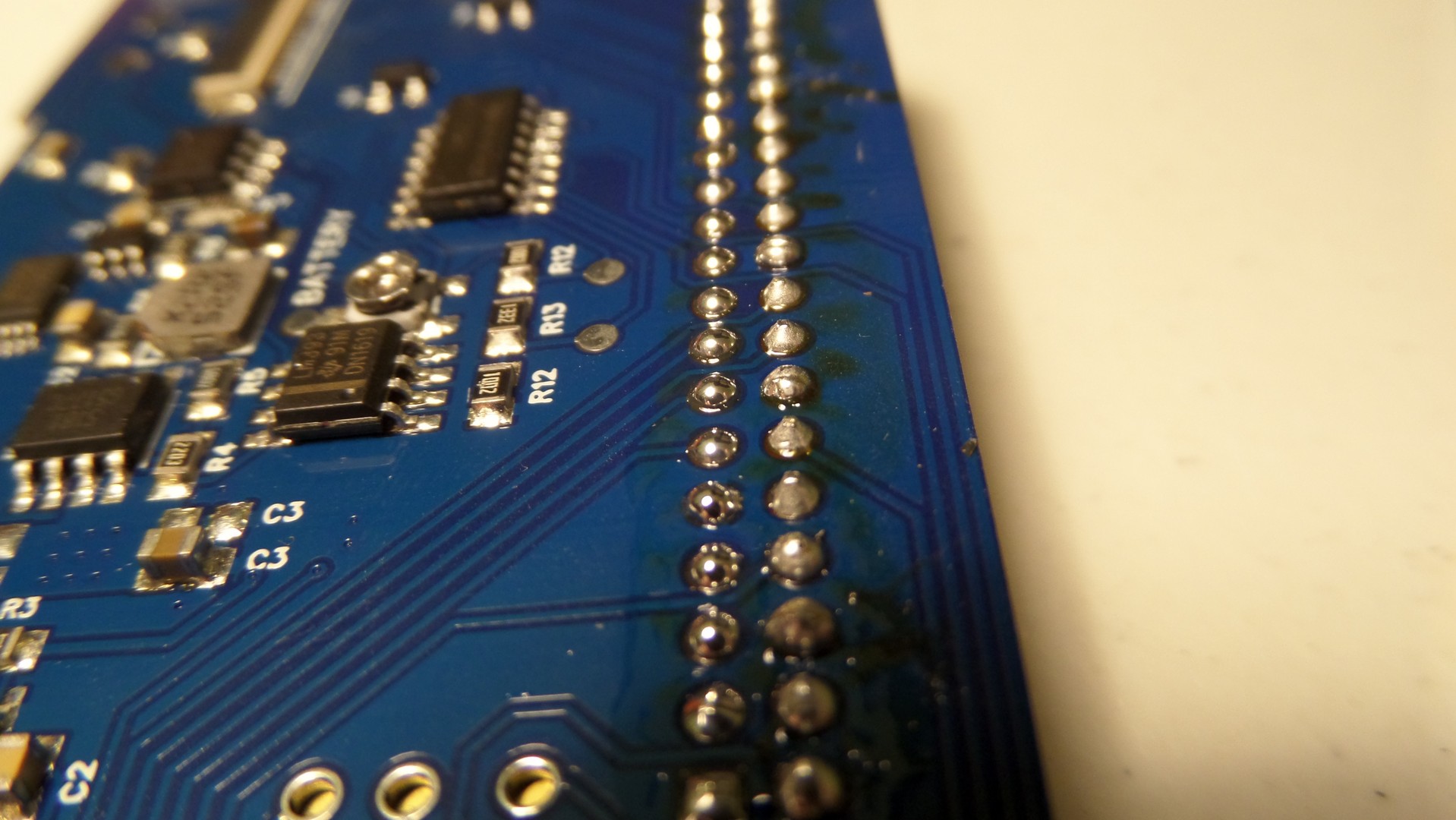
Go back and do the same thing for the other 20 pins.
I did something for comparison here. The left side is normal leaded solder, and the right side is high quality lead free solder. The left side took about 30 seconds to do, and the right side took about 10 minutes. The left side was easier and came out much better.[spacer height=”1px”]
Here is the bottom all soldered up.
[spacer height=”1px”]

One more important step. Use a rag and some rubbing alcohol (91-99%) to clean up the flux. It doesn’t make anything work any better, but it looks a lot better and is far less sticky.
[spacer height=”1px”]
Trim the Plastics
This plastic piece has to be removed from the PSP case to make room for the board.
[spacer height=”1px”]

[spacer height=”1px”]
Optional Feature – Headphone Jack

Install the headphone jack into the case with hot glue. This jack comes from the PSP’s old board. If you think you’ll have trouble removing it, you can also purchase one here.
[spacer height=”1px”]

[spacer height=”1px”]

Solder wires to the jack.
[spacer height=”1px”]
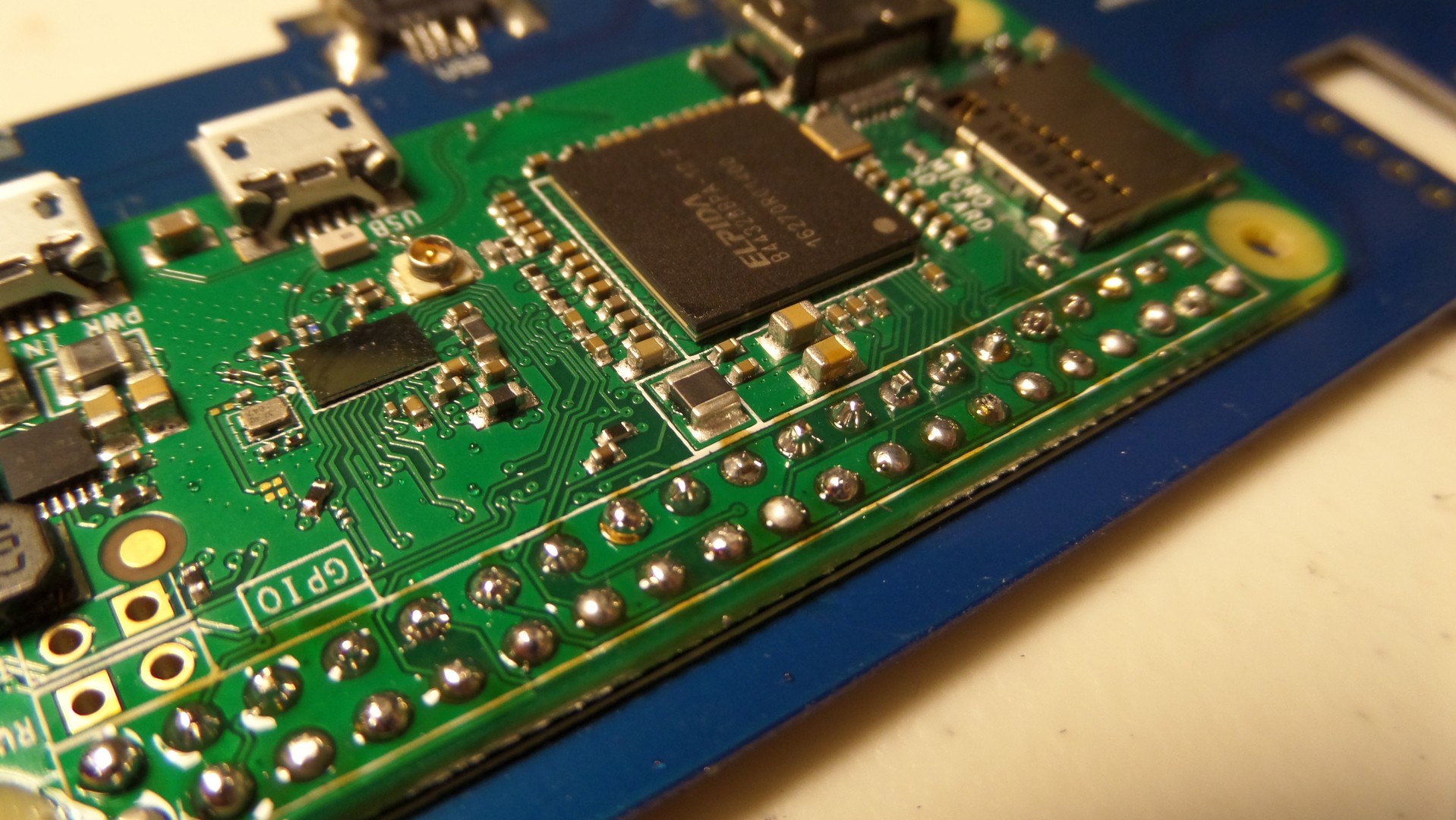
Optional Feature: External microSD Card Access
Please only do this once you have everything else soldered up and tested. I seriously recommend inserting the microSD card directly into the Pi Zero and verifying everything boots before continuing with this part. This has been the cause of nearly all the issues people are having.

These holes are for the microSD card breakout. This allows you to relocate the microSD connection elsewhere on the PSPi. It’s not required, but it’s really convenient to be able to swap the SD card out easily.
[spacer height=”1px”]

This part definitely requires flux and lead solder.
[spacer height=”1px”]

Use an ohmmeter to verify the solder joints are good. The SD card pins match the unsoldered pin holes below it. When checking, skip the 4th pin from the right. The microSD has only 8 pins, and the SD has 9 because there are 2 GND pins.
[spacer height=”1px”]

Hot glue your SD to microSD adapter into the empty compartment on the left side. This isn’t part of the kit, so you’ll need to get one when you buy a microSD card.
Don’t fill the whole compartment or you won’t be able to slide the cover off to remove the microSD card.
[spacer height=”1px”]

[spacer height=”1px”]
Optional (but recommended) Feature: External USB Connector

[spacer height=”1px”]

Solder wires to these two pins on the microUSB adapter. This USB adapter is included with the kit.
[spacer height=”1px”]

[spacer height=”1px”]
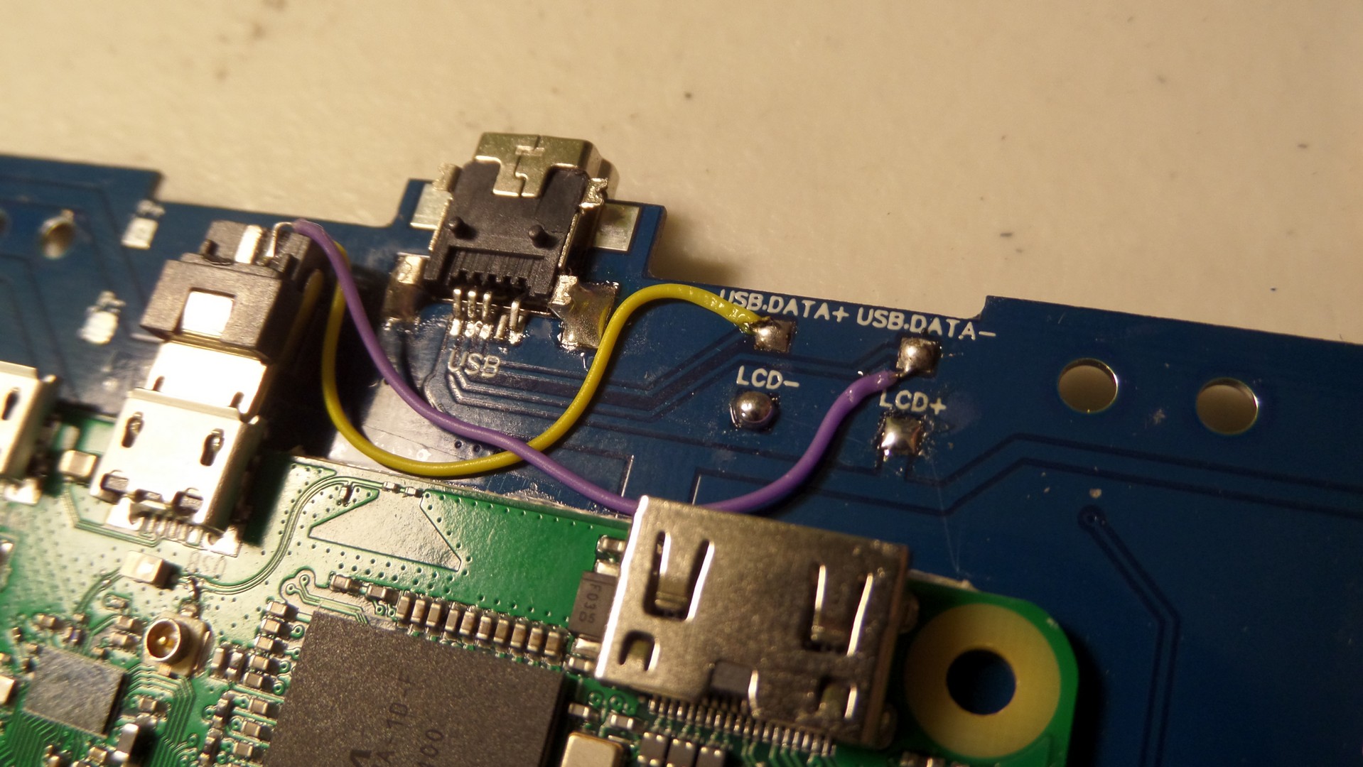
Solder the two wires to these pads on the board.
[spacer height=”1px”]
Board Installation

Install the board, attach the white power connector, and slide the FPC-24 cable into the open connector.
[spacer height=”1px”]
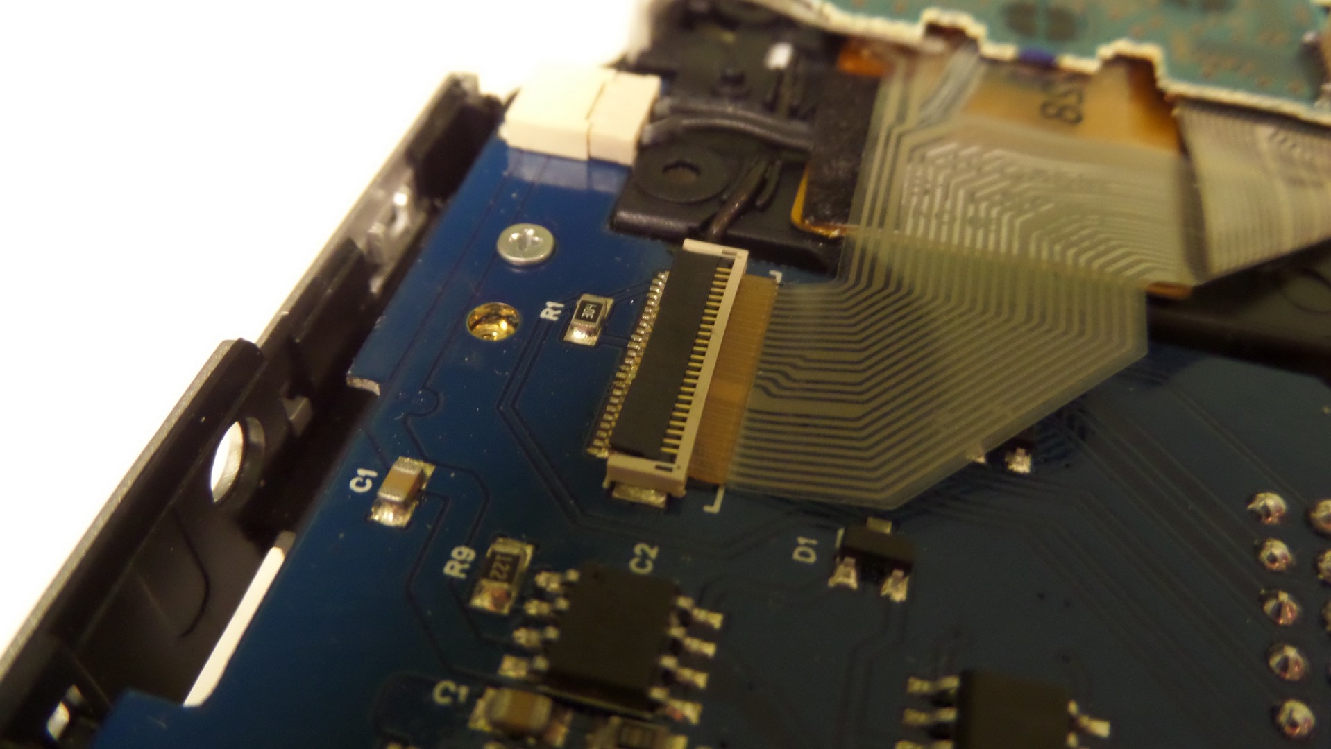
Flip the black piece down to lock the cable into position.
[spacer height=”1px”]

Repeat the process for the left side controls and the FPC-10 connector.
[spacer height=”1px”]
Finish Connecting the Headphone Jack

If you chose to attach the headphone jack, then solder the three headphone wires to the board pin holes labeled H.L (headphone left), H.R(headphone right), and HG(headphone ground)
[spacer height=”1px”]
Finish Connecting the External microSD

If you chose to attach the external microSD adapter, let’s start soldering it up.
[spacer height=”1px”]

Solder a wire to each of the SD adapter’s 9 pins.
[spacer height=”1px”]

And attach the wires to the board. Isn’t that convenient?
[spacer height=”1px”]
Soldering the Speakers
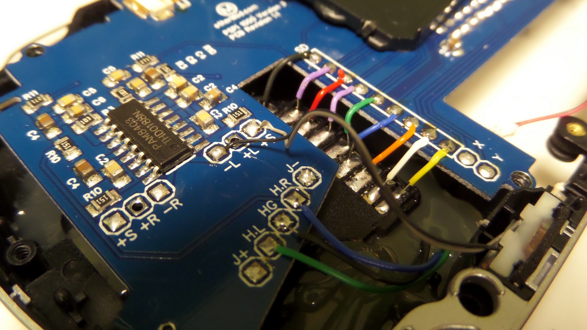
Solder the left side as shown. Just strip the headphone wire back a little to expose it. Attach them to the -L and +S on the right if you want reduced volume (and reduced PWM noise), or to -L and +L if you want much louder volume (and more PWM noise)
[spacer height=”1px”]
 Do the same thing for the right side speaker. You’ll need to solder some extension wires to that one, since the wires are a little short.
[spacer height=”1px”]

And flip the left side control board into position.
[spacer height=”1px”]
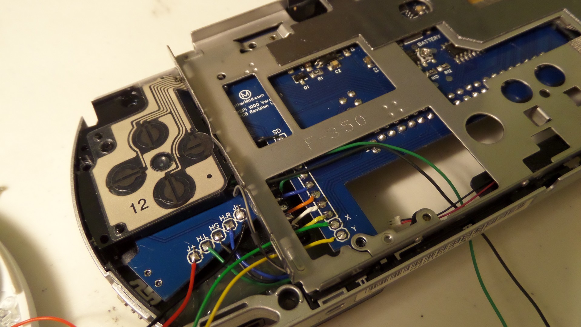
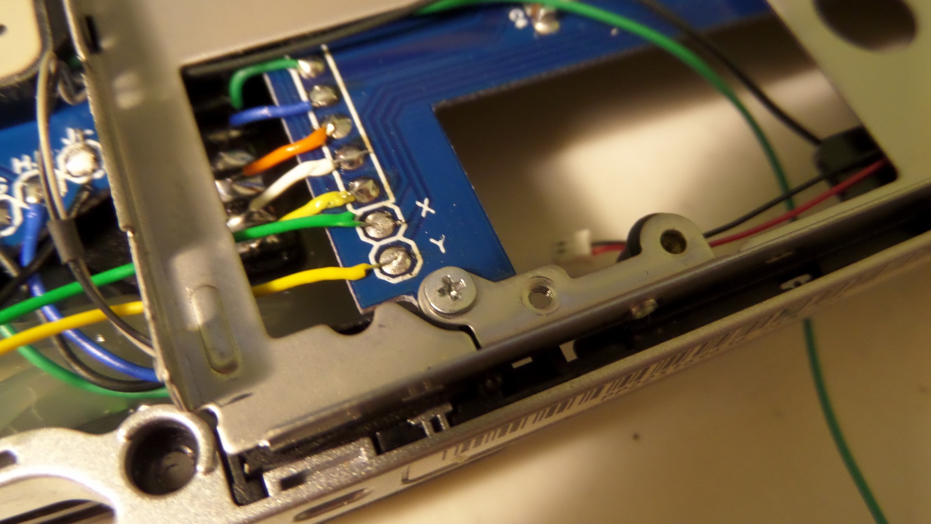
Joystick

Solder 4 wires to the joystick pads. Use some hot glue to secure and insulate them.
[spacer height=”1px”]

Solder the red and black joystick power wires to J+ and J-.
[spacer height=”1px”]

And solder green and yellow to X and Y.
[spacer height=”1px”]
Putting it Together
Install the LCD bracket. Make sure you break off the part that usually sits below the joystick. Just bend it back and forth a couple times to break it.
If your bracket is bent at all and you’re afraid it might cause a short circuit on the board, you can put some tape over the board to keep it insulated.[spacer height=”1px”]

Install some screws
[spacer height=”1px”]
[spacer height=”1px”]

[spacer height=”1px”]

[spacer height=”1px”]

[spacer height=”1px”]

[spacer height=”1px”]

[spacer height=”1px”]

Install the LCD panel into the bracket. If there is a sticky pad on the back of the LCD, you should remove it (or at least most of it).
[spacer height=”1px”]

Install the control board at the bottom of the LCD.
[spacer height=”1px”]

Flip it upside down and install the controller board onto the FPC ribbon.
[spacer height=”1px”]

Solder wires for power and composite signal.
[spacer height=”1px”]

Solder the composite video wire to the pad on the Pi.
[spacer height=”1px”]
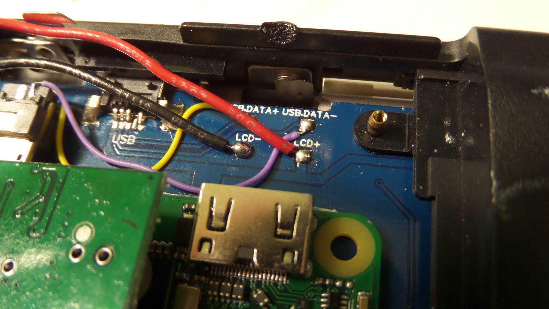
Solder the LCD power wires to the pads on the board.
[spacer height=”1px”]

Remove the stickers and plastics from the two batteries and solder them together.
Be careful with the batteries. They have protection circuits on them, but that doesn’t mean you can’t still cause damage by short-circuiting them[spacer height=”1px”]

Put the top cover on and put the remaining screws into place.
[spacer height=”1px”]

[spacer height=”1px”]

Solder the battery wires to the board. Take your time doing this and make sure you don’t hook it up backwards. Bad things will happen.
[spacer height=”1px”]

[spacer height=”1px”]

The LCD controller position is close to the Pi, so it’s a good idea to use hot glue to keep everything secured and prevent short-circuits.
[spacer height=”1px”]

[spacer height=”1px”]
And here it is.
I look forward to seeing how you guys decide to build your own.
[spacer height=”1px”]
One final thing to note is that the system does run warm, especially if you’re playing and charging it at the same time, and the new Pi Zero W runs even warmer. It’s a good idea to add some vent holes in the back cover so the heat can be removed.
Software Configuration – This is a work in progress
Download the following files:
Config.txt
GPIO Buttons
GPIO Shutdown
[spacer height=”1px”]
 Insert the microSD into your computer and copy a fresh RetroPie image. The RetroPie has lots of documentation on how to do that.
Copy the downloaded config.txt to the boot drive
[spacer height=”1px”]
[spacer height=”1px”]

Extract the Buttons and Shutdown zip files and copy to the same boot drive.
[spacer height=”1px”]
[spacer height=”1px”]

[spacer height=”1px”]
[spacer height=”1px”]
Insert the microSD card into the PSPi and attach a USB keyboard. Power the system on and let it do its thing. It may reboot a few times to resize partitions. Once it fully boots you should see the controller configuration, but now is not the right time to do that. Press F4 on the keyboard to exit to the command line. The following commands have to be typed exactly as shown here. Don’t capitalize anything and don’t miss or add spaces.
Type the following command and press enter:
sudo bash /boot/setupcontrols.bash
Follow the prompts to install it.
Then type this command and press enter:
sudo bash /boot/setupoff.bash
Again, follow the prompts. Reboot the system.
You’ll be taken back to the controller configuration, and you can use the buttons to configure the buttons now. I’ll post details showing which buttons I usually configure for each function, but this can be a matter of preference. When you get to a button that doesn’t get configured, just hold any other previously configured button to skip it. The analog joystick doesn’t get configured, it works from the D-pad configuration.
[spacer height=”1px”]
Common Problems – This is currently being updated
It powers off a couple seconds after turning it on.
Possible Cause 1
Software configuration. 90% of the issues so far have been software and were resolved by repeating the process detailed in the guide.
Solution 1
Make sure the SD card was imaged properly. Use Win32DiskImager or a similar tool to copy the RetroPie image to the SD card.
Make sure you copy over the modified config.txt file and overwrite the original one. There is already a config.txt, so you must overwrite it.
Possible Cause 2
The solder joints between the Pi and PSPi need some work.
Solution 2
Test for a connection on each pin between the top of the PSPi and the bottom of the Pi Zero.
No image on the LCD
Possible Cause 1
The SD card wasn’t imaged correctly.
Solution 1
Use Win32 Disk Imager to copy the RetroPie image.
Possible Cause 2
Connection issues to SD card.
Solution 2
If you’re using an SD to microSD adapter to relocate your microSD slot, then check all your wires. Make sure none are disconnected, and certainly make sure no connections are shorted. Try inserting the microSD card directly into the Pi to rule out wiring issues.
Try and look into this if you can, should be able to grab data using the pi from it and control the led from the pi as well.
https://ripitapart.com/tag/iphone-gas-gauge/
Unsure of space for the battery but dependent on the generation of battery you use as well.
As with all handheld projects space inside is ALWAYS a factor as you have well pointed out.
I was looking at doing something like this with my project to ensure room for the iphone battery and allowing for more room for other add ons
http://technabob.com/blog/2009/06/07/how-to-make-your-psp-less-portable/
Just a few suggestions, Once I get more of an idea of what everything I want inside I will be making my own. Can’t wait for the custom pbc to be made.
Thanks for the info. Size would probably be an issue with my project, but the battery is interesting. It would be really great to see a PSPi with a keyboard. That would open up many other possibilities, since at that point it really would be a fully functional computer. I don’t see a reason to destroy a PSP just for the keyboard though, maybe just make a custom shell for the keyboard. Keep an eye on the page for updates on the PCB.
You can buy aftermarket shells for the psp for about 10-20 $ I did this with mine since the case was cracked
https://www.ebay.com/itm/141042677869
Very cool. I hadn’t considered aftermarket cases. I like that clear one for the PSP 1000.
Look i know tge space is verry small so you’re using the pizero but i was thinking about using pi3 after removing usb and Ethernet ports just to add more horse power to the pspi3 😉
You might consider adding a an analog and l2 r2 … Sure will make the process of making the new one slow but will make it perfect
The Pi 3 is much bigger than the Zero. It would be a very tight fit, and it’s possible it won’t fit at all. I don’t have a Pi 3 to verify, so someone else would have to try it.
I am working on the analog circuit, and I plan to include it in the next build.
from what I know the pi 1/2/3 all have the same physical board size but even so the size of it and the heat as well is daunting to put in a psp
“Shut up and take my money!”
This is just outstanding. I’m bookmarking and keeping tabs on this. I’ve been waiting for something exactly like this forever!
Amazing work.
This is the type of comment that keeps me motivated. Thank you for the kind words.
Hey,
Best of luck with your v3! If you get the board finished I will want to buy one, will you sell them?
I’m about to finish my build based on your v2, but I realize I cramed too much stuff in there with a wifi dongle, teensy controller, usb audio and a USB hub to connect it all. I will probably have to use glue to keep the UMD hatch closed, which lowers the show-off value 🙁
In your PCB design, are you re-using the little rubber thing that connects to the analog stick in the original PSP? I’m finiding it hard to route the cables with the screen mount attached.
Cheers!
Yep, I’ll sell them. I’m only making them at all because so many people asked me to.
I hope to be able to sell them at a reasonable price. I’m doing a little bit of a redesign on it right now because it’s going to cost me a fortune to get the prototype made. I’m hoping to knock off a couple square inches. My cost is probably going to be about $50 per board counting all the parts, and I’m not sure how many people are willing to pay that much.
I’m not going to use the rubber connector. I plan to just solder to the joystick connections. It’ll still probably take a couple hours to build one of these with the board, since the power supply board, audio amplifier, and SD slot will need to be soldered up.
Please keep up the work, I’m a noob but am ok at following instructions, I would love to make something like this for my son as a present, so keep going! I will buy one when you’re finished. I was going to do a game boy conversion, but I like your version much better.
you should make and sell these so that people who don’t know how to make these or don’t have the abillty to make one can also have one
you should have a normal usb port on it insted of the psp one
and a port to conect your pc to it as well (like a micro usb port on the pi)
and how much will you sell it for because i would like to buy one if it had a micro usb port on it, at least one normal usb port, able to conect to WI-FI, and all the psp buttons, and I’ll think of some other stuff too
The miniUSB port already connects to the Pi, and works just like the microUSB. From there, a miniUSB to regular USB adapter is used to connect to other devices. Wifi isn’t a priority right now, but it’ll be included in a later version.
Hi friend.
Great work! I love it!
I have a question. What should be the value of the ferrites in the audio circuit?
At first I thought you were asking what their purpose was.
I’m still working determining that. Testing a few circuits this weekend, then I’ll post an update.
Ok. I’ll wait for it.
Sorry. Maybe I didn’t use the right words. My primary language isn’t English ^^
Thank you.
Hi, I found your project when searching for pi zero handhelds. I was sure I wanted to build a gameboy, but your project makes me doubt! Really nice work. For the gameboy I am following a topic where Kite is making a custom pcb with alot of features built in. Mabye it can help you! He also built in the screen controllor. Have a look at the topic.
http://www.sudomod.com/forum/viewtopic.php?f=9&t=243
I’m working toward that. I’ve even received some help from the guys on the Sudomod forum, including Kite. I don’t have the amount of PCB design experience that they have, but I’m working toward it. The design process takes me a lot longer than it would take them.
Hey im very interested in those kind of projects and love to experiment, as 50$ is quite a lot for me im always looking to find cheaper ways, maybe you can tell me what this PCB would cost if made on pcbgogo.com?
Or if i can do one with this http://www.instructables.com/id/Making-A-Customized-Circuit-Board-Made-Easy/
I’ve tried that in the past. It works great with larger routed wires, but fails pretty badly on small ones like what I have here. That’s my experience at least.
I’m already looking into different companies for the final board. I’m still prototyping, and I’m sticking with the USA based company OshPark until the final design is hammered out. Their prices are a higher than the Chinese companies.
If cost is an issue for you, you might be interested in the smaller boards I’m getting made. They require a little more soldering but the cost is less. I expect them to start arriving in a couple weeks.
Im not scared from soldering 🙂
(Xbox 360 Controller modded,
Xbox 360 console RGH 2.0,
Pi2 + APA102 LED TV Ambilight)
Hey bud, great work. I have an old psp 1000 that I plan on doing this to. $50 is doable considering parts, laybor, and all the work that will be taken out of the equation for the buyer. I plan on buying one once you have them completed. You’ve probably been asked this before, but have you considered using the screen that comes in the psp? Is the rewiring not worth the effort considering the screen you used can be found sub $20? Keep up the good work man. I know it is helping me along with many others!
It’s a combination of problems. When I first started the project there weren’t any good ways to interface with the original LCD. Now there is an HDMI driver board that can do the job (I have one on the way actually so I can test fit and modify it), but the cost is 2x to 3x the cost of the composite LCD. The video quality on the HDMI board is going to be much better than the composite, so it’ll be a decision over which one is more practical for each person.
Can you give me the link to this HDMI driver board? And thanks for the info bud. Keep up the good work man!
This is the type I ordered
There are slightly cheaper ones out there if you shop around. It going to be heavily modified to make it fit. Even then, I’m not 100% sure it will fit.
What about the MAX8815?
You could use this IC for boost the battery to 5V. It can provide up to 1A output.
https://datasheets.maximintegrated.com/en/ds/MAX8815A.pdf
Look at the circuit on page #9
I’ve researched that one before and it’s one of my favorites. The only problem I have is the cost. $3/chip is a bit high. Not saying I won’t end up using it, I’m just not ready to make that call yet.
True… It’s quite expensive for only a component.
Something like this would be ideal.
http://www.ebay.com/itm/DC-DC-Step-Up-Boost-Module-1PC-New-1A-Converter-3V-to-5V-/200983543561?hash=item2ecb8d7f09:g:yyMAAMXQuTNTOMs-
If they can sell it for a dollar then the parts must be cheap. That’s appears to be the same step-up components that are used in the module I used in my builds. I’m trying to find a schematic for it so I can determine efficiency and how much power is wastes when shut down.
I think it’s the LM2735, which is about 85-90% efficient and has good shutdown current.
I was thinking in the A7530, which is about 96% efficient. The output current is up to 600mA, that I don’t know if it’s enough for this purpose.
http://www.ebay.com/itm/262568605146?_trksid=p2060353.m2749.l2649&ssPageName=STRK%3AMEBIDX%3AIT
http://www.electroschematics.com/10935/pfm-module-circuit-surgery/
600ma is probably going to be too low. 1a is really the minimum. 96% efficiency would be great though.
Your project is amazing! Very inspiring! Thank you very much for sharing!
I was also wondering how to connect the joystick and keep its analogous nature. So far I have not found anything about Adafruit’s Retrogame supporting I2C or SPI devices. I hoped that you could find a simpler way than writing a special driver for the joystick… 🙁
Still wondering why your way does not work because of delays, since all frequencies(sampling and transfer) must be more than sufficient. Problem could be in the way your driver is written. Maybe I could help with that…
So I’m using a python script that utilizes spidev and uinput. It polls the MCP3002 (using spidev) at whatever interval I choose, and returns the values of 0-1023 for each channel. I can then use uinput to send those values to the OS, but that is where I’m stuck right now. Uinput can send the values to ABS-X and ABS-Y, but I haven’t learned what to do from there. It can also just send Up, Down, Left, or Right, and possibly do that for a varying about of time depending on the value of the joystick position, but this is another area I would have to research more.
This is taking a little too much of my time right now, time I should be spending on the Version 3 board. I’ll probably have to address this later, once I get the board finished, and just add it to a later revision.
Oh and when I said it was causing delays I meant that it was delaying me from getting the board finished. Python is reading the values of the MCP3002 with no problems.
Amazing! And a big yes! I would buy it.
I am truly amazed with the effort you are putting into this.
Sadly the Raspberry Pi Zero’s are hard to get in my country, got 2 of them but payed way too much for them.
Keeping this bookmarked!
Thank you for the comment. I’m working hard to get this ready for you guys, and these comments keep me motivated.
Forgot to ask, what version of the PSP are you using for this project? I got a 3004 taking up dust 😛
1000 series right now. 2000 and 3000 series boards will come at a later time. I’m working on 1000 series kits that will include all aftermarket/used parts (case, connectors, etc) for anyone that doesn’t have a broken PSP 1000.
will you be selling the all-in-one PCB alone or just in the kits ? and will it be pre-soldered or bare ? Btw… g8 job on it, i will be buying one no matter what when it is ready 🙂
Both alone and in a kit. I plan to sell all pre-soldered, but I can sell empty boards if there is demand for it.
I like to buy empty board but getting all the components front you .just to get my hand on
i am in 100% as soon as you finish i will buy the first pre soldered board 🙂 keep up the amazing work!!!
Thanks. Hopefully the wait is almost over.
Same. Im already on ebay looking for old PSP 1000 to buy for this project. Im all about pre soldered as well.
Have you thought about using a raspberry pi 3 but remove all the ports you don’t need to save space.
I have, but my time is very limited while I work on the kits. I want to try a Pi 3 once things settle down.
This is awsome. I just found this website yesterday and am so excited to make my own pspi. I can’t wait for this board to be avaliable. Does anyone know wifi will be added to the pi zero in this project ? This would be cool
Please keep up the good work… My friend was selling a Raspberry pi 3 and during my research i stumbled upon this… watching your videos im extremely interested… im looking forward to the final version of this project… i would pay for something like this…
Just bought an PSP and waiting for the PCB release … keep up the good work, you had made an very good job so far and thanks for making things like this possible.
Just an idea, I spotted this PSP knock off on ebay for around $30. Can we build retropie using that as a foundation? It comes with screen, battery and body.
https://www.ebay.com/itm/142169844722
I really have no clue. This is the first time I’ve seen that knockoff. That’s really cool though.
I saw your posts on the retropie forums and was thinking “wow I wish he would sell this as a kit”
and now I find out that you are FANTASTIC!
I am a noob at all of this but I am very excited about the idea. As soon as the kit is ready I am all over it
A few quick questions
What would I need to finish the build?
Will the fact that I am in the UK be a factor?
Is there any plans to sell complete finished systems??
Thanks for all the great work!!
The Pi Zero, SD card, SD adapter, and LCD should just about cover it.
UK will not be an issue. When the audio boards arrive I’ll open up international shipping.
I am documenting a few test builds, so there is a good chance one will be listed on eBay.
Just got my psp last week. Any Eta for final boards yet
All I can say is that I have the circuits 100% designed. I’m in the process of routing everything, and it’s very time consuming. Every tweak causes a dozen other changes. I can say that the second (and hopefully final) prototype will be ordered soon, but I can’t say how soon.
Do you plan on having a way to have wifi connectivity? You could have a USB hub. Then you can just attach a USB wifi module. I am sure there are easier ways.
The features on this board are locked in, and nothing else is being added. Wifi is something I’ll consider adding to a future version, but I’m focused solely on getting this ready to go with the current features.
That being said, a USB hub can be attached externally to the miniUSB port.
I’m excited about this. I can’t wait until you have it completed and ready to buy!
i am really curious about the soldering gun that you are using can you provide the details and/or a amazon link i like the vapor extractor
eBay Link
That’s where I got it from 4 years ago. It looks a little different now, but it’s still called the 9020-XTS and the features look the same.
just waiting, hope everything is going smooth, I know about the time it takes to develop and send out to PCB companies, I have dealt with OSH Park,
and was a good experince. So I will hang until your PCB come in. Happy Holidays and a safe New Year !
It’s also that I’ve had to do a couple prototypes to work out the bugs. I’m definitely ready to have this finished. Hopefully it won’t be much longer.
Amazing. I started to price up your components list from version2 on ebay, and with the time saving $50 is a bargain.
Im in the UK and will order one as soon as theyre ready
Need to sell white faceplates with you kit so i can do this
http://k4z1.deviantart.com/art/The-SNES-PSP-Custom-faceplate-339850295
Ohhhh I love that paint job
My 1st project was a Pi3 Joker Bar Top arcade. While I’m 1000% satisfied with how it turned out, portable has always fascinated me.
What you have done is incredible! Lot of detail for a small board. I already clicked on your alert button in the store, do you have a waiting list? If so please add me. Excited to start this project!!
No waiting list yet. I’ll open up pre-orders when I hit the button to order the final board.
Thanks for the reply, I’ll keep checking.
BTW…been looking through your tutorials, nice job!
Great job thus far, do you know what the difference is between the psp 1000 and 2000? i have 2 2000 i would love to bring back to life
The pinouts and clearances are different. It’s something I’ll be looking into once I get everything else caught up.
Do you plan on sharing the pcb files or schematic? If not that’s fine! Looking forward to being able to order it!
Maybe some day. I’ve put 6 months and a lot of money into these designs, and I need to recoup a little of the investment before I share it.
Hello everyone,
I hope you will receive your order asap !!!!!! 🙂
I have a question (maybe stupid question…). Is it possible to keep the original LCD display of my PSP?
I hope my english is good enough…
It isn’t possible right now because there is no driver for it yet. Maybe sometime in the future.
prototype 2 looks great, is it the final color for the pcb?
i really liked the purple pcb from prototype 1.
i like the audio on/off switch, but will the vol. + and – on the psp front work?
looking forward to buying one from you 🙂
I haven’t decided on the final color. This was green to lower the prototype cost.
The volume buttons, start, and select are all wired to GPIO pins, so they can be programmed to do anything.
Great news! Can’t wait to get started on this project!!
https://www.google.com/url?sa=i&rct=j&q=&esrc=s&source=images&cd=&cad=rja&uact=8&ved=0ahUKEwiE26_7lMfRAhVX6WMKHeAEDX4QjRwIBw&url=http%3A%2F%2Fwalkingdead.wikia.com%2Fwiki%2FFile%3AShut-up-and-take-my-money.jpg&psig=AFQjCNGLXmp1wvEP28s9SZlPc1f-UGybnw&ust=1484673241834731
haha, I should have waited. Oh well will just need to do it v3 once it comes out.
Cant wait to get hold of this board!
Can you post pictures of how this sits inside the PSP please.
How does the LCD driver fit in?
Sure. I’ll post some pics later.
It sits right on top of the Pi. There is plenty of room for it now.
Hi, im currwntly designing a vustom board for the psp 3006. it uses allwinner a13 olimex system on module, rgb screen, it will have 2 memory cards and other cool hacker friendly features. Now its in schematics stage, but gonna start to design the board soon. Didnt use the raspberry pi bcoz the som had native rgb support and more interface and horsepower. and ofc it would be too easy then xd.
Nice. I hope you keep me informed of the progress. I know how complicated the schematics and PCB designs are for these chips, and I would love to see how it turns out.
What PSP has this been tested with. Going to start getting the hardware now for v3
The original 1000 series only
Amazing work – what a cool project, I’m definitely onboard for this, though I’m not 100% sold yet, I’m a stickler for image quality…
Since you obviously have skills with creation of PCBs and circuits, what is stopping you from creating some kind of interface that allows use of the PSP’s (gorgeous) LCD? I don’t mean to imply that this is *easy* or trivial, and I understand that there is no driver for the LCD, but couldn’t the Pi just output HDMI and then you convert that signal to whatever format (LVDS?) the PSP LCD uses?
Probably a dumb question, but have you spoken to Ozone (http://assemblergames.com/l/members/ozone.64655/) on the Assembler Games board? He’s making an HDMI-out mod that is broadly compatible with various consoles and portables, so perhaps he could assist you with reversing that process for the PSP LCD? His board is not suited to your mod, it’s meant to tap into the native RGB signal of the consoles, but it seems like his knowledge of HDMI signalling and conversion might still be useful if you wanted to find a cheaper/easier solution to using the original PSP LCD…
From what I know (which is limited), the brute force approach to this would be to use an FPGA chip to convert the HDMI out from the Pi to the signalling format of the PSP LCD. This would then forgo the need to actually write a driver for the PSP LCD, since the Pi just has to output regular old HDMI.
I ask because if this hurdle could be cleared it would really enable this project to be the absolute king of Portable (Zero-based) RPis. The idea of doing this mod for $50-$70 is great, but when you throw in the one of those $40 HDMI converter board + LCD combos the cost creeps north of $100 and it becomes a little hard to swallow.
Do you have plans to eventually release a kit that uses the PSP’s original LCD or is that just plain unlikely/impossible?
Thanks for all your hard work – I can’t wait to see where this project goes!
I’ll look into the work Ozone has done. I’ve been contacted by 3 separate people saying they are working on schematics to interface HDMI to the original PSP LCD (mostly because the PSP’s screen is so cheap and good). So far nothing has come of it, but my hope is that they can make something I can integrate. My goal definitely is to integrate the LCD controller, but it won’t be easy and it won’t be soon.
I made the decision not to focus on it right now. The composite LCD gets the job done, and they only cost $15. Is the image quality perfect? No, but it is very good. If I focused all my time on the LCD, it would easily mean another few months of research, design, and testing.
I fully intend to eventually release a board that uses the PSP’s original LCD, I just can’t be sure when I’ll be able to make it happen.
Understandable – as I said I know it’s not an easy goal to achieve since the PSP’s LCD is proprietary and therefore not easily communicated with.
Still, don’t be misled – I do think this is a great project, and as soon as you get a solution that either uses the native PSP LCD or (cheaply) uses some kind of external LCD with all-digital video, I’m definitely buying one! I love the idea of getting this set up so that in the future I can just swap out Raspberry Pi modules (assuming they ever release another version of the RP Zero).
Another somewhat similar question – since you’re already using a custom breakout board, have you considered investigating whether or not it would be feasible to adapt the Raspberry Pi Compute Module? They just released the new Compute Module which uses the RP3’s processor, and its form factor is close enough to the RP Zero that it seems very plausible to adapt a future revision of your breakout board to use the RCM intead of the RPZ.
Good luck with future revisions, I can’t wait to see what else you come up with!
Yes, it is feasible. The only concern is the added power requirements and added heat. It’s on my list of possible future projects.
I’m so impressed with what the little pi board can do. Currently I have my LCD and pi wired up to the Psp power socket and playing with a wireless keyboard. Screen quality is fine, although a little fuzzy at the command prompt. I may invest in a mini Bluetooth and WiFi dongle and have it connected inside, but will wait to see if there’s room for that.
My money is waiting for you Adam!
Great job!
How long does the battery last with continuous play?
I have a couple of PSP1001 units that are kind of useless for anything anymore so this would really repurpose them and a much larger screen with a nicer playable feel than converting a Gameboy!
I get a few hours. I’ve gotten up to 4 when I run the battery all the way down. You will definitely get at least 2, but it depends on which LCD you choose (some use more power)
Please go with blue, it highlights the board traces better and looks infinitely cooler.
Awesome! Glad people are jumping at your product. Can’t wait to get mine.
will you sell the all-in-one Pcb alone outside of the kit later or only in the kits?
I have no problem doing just the boards. I’m here for you guys. Once I get the kits stocked I’ll make another item for just the board.
Could you give me sth like a mechanical drawing with the exact measurements of the pcb? Me and a friend of mine are working on a fully custom psp case for your zero project and a variation for a Pi3.
We just need sth to work around with. Providing the measurements of your latest custom pcb would help a lot.
Greetings from Germany
Looking good!
How do we go about soldering the pi to the board. Will the board have pins soldered in or will we need to do that?
The pins won’t be soldered on, but I’m including two 20-pin headers with the kits to make the process a little easier. Basically just solder them on and trim the pins to the right height (with flush cutters the process takes no time at all).
I wanted to pre-solder the headers, but the solder tends to bleed down and it keeps the Pi from mounting flush.
Cool, I would imagine you would go crazy soldiering 60 lots of 40 pin headers!
Now we have the Pi Zero W so there is no longer the problem of no WiFi 😀 Hows the Headphone audio quality on this board? Is there a way to change the volume without going into the Config of the Pi?
-Dylan
It’s decent. The audio is filtered before reaching them, so it gets rid of most of the PWM noise.
You should be able to use the volume controls. If I remember right, it’s select + volume button. The software is all there in RetroPie. As with everything, it’s got to be configured.
I was thinking of putting something like berry boot (http://www.berryterminal.com/doku.php/berryboot) on it so I can use Kodi with it as well so I have a portable gaming center and media center in the palm of my hand, all that I need to do is put the movies on a USB stick, plug it in and enjoy!
the above download config.txt could not be downloaded
Typo fixed
Will the heat sinks fit?
Maybe a thin one, but I doubt you need one much since this board absorbs basically all the heat. What are you trying to use?
A mild overclock to run Neo Geo.
I forgot to hit reply.
What issues did you have with the Bluetooth? It’s working on mine although it seems to disconnect and reconnect when launching one of the emulators.
It changed the function of the TX pin and caused the system to power off a few seconds after powering on. I had to add some code to config.txt to keep the pin high after bootup. After a few hours of testing it appears that this is all it took to fix my issue.
did you put an Wi-Fi antenna socket on your pi zero w? because my pi zero w doesn’t have it :-/
Very attentive of you. I added it out of curiosity since the PSP has an antenna on the right side.
Stupid question that I think I already know the answer to, but want to ask just to make sure. To add a wireless charging receiver, the receiver would attach at the battery pads on the board, correct?
Also, any idea when the updated config.txt and software configuration will be available/completed?
Actually really good question. I put two pads on the back labeled P+ and P-. They are for wireless charging or solar charging. I just wasn’t ready to advertise it.
I’ll post the config.txt tomorrow.
My bad for letting the cat out of the bag on that one. lol
My main concern with it is the amount of heat the wireless charging generates. You really can’t charge it while it’s on or things will overheat.
Well with using the receiver, you wouldn’t be able to play while charging anyways. The receiver has to be within 7-8 cm (if I remember correctly) of the charging pad to charge.
Yeah that’s true. The main concern would be someone turning it on then setting it on the charger. From my testing it’s more like 1-2cm.
When assembling the Headphone Jack, I noticed you have a solder joint across 3 of the pads (in your picture above). Is this intentional?
It took me a minute to figure out which picture. No, it wasn’t intentional, but I didn’t bother fixing it because those pins go to the RX/TX pins on the other area of the headphone jack and those pins aren’t used for anything.
Thanks!
Well my kit has made it to the UK, but our wonderful postal service is hanging on to it for some reason 🙁
I now have my board installed and running. One important thing that had me stumped for a while,its important to copy the config.txt onto the sdcard, otherwise the pi will turn itself off straight after you turn it on. I just need to get a new Psp chassis now as I’ve broken a couple of lugs over the months trying things out for fit.
Excellent. I’m taking in all the feedback so I can improve the guide.
He I used the display you recommended, and I’m getting lots of snowy static on my display. Used the correct config.txt and triple checked all setting. It gets worse as boot-up progresses, and becomes unusable once fully booted. Could it be a shot, or any ideas how to fix it?
Could be that the filtering needs some help. These guys are changing their designs so much that I can’t keep up, and I’d need to see a pic of the board to know what needs to be done. What I expect to be the problem is that an inductor is needed on the output of the buck converter to smooth out the switching (usually 300kHhz or so). A 100uH inductor and a capacitor above 20uF usually does the trick, and it’s possible they are already on the board. Post some pics in the forum and I’ll look.
Hi:
first of all thank you for doing this, second of all… can you tell me what components do I need to complete this pspi3? I know:
1.- pspi3 pcb (made by you)
2.- psp case
3.- PSP 1000 Headphone Jack
4.- the screen
5.- blackberry batteries
is there anything else?
Everything you listed, except the batteries. They come with the kit. Headphone jack is only needed if you think you’ll have trouble removing your original one.
You do need more than just a PSP case (not sure if that’s what you meant, just making sure you know). You need the internals like the LCD bracket, small boards used for controls, etc. I recommend buying a dead PSP from eBay instead of trying to piece one together.
Just got mine in just waiting for the psp. Is it possible to wire up the battery without taking off the plastic?
It will be a really tight fit if you leave the plastic on. You might be able to make it work, but I wouldn’t recommend it.
In the next one are you going to try to integrate the volume buttons on the psp? And maybe using the home button as a function button that acts as though you press start and select to return to the previous page
Might be a silly question but can i use the pi zero W?
thanks
Yep. Zero W is what I use when I build them.
Brilliant cheers
hi, I tried all the solutions to the pspi shutting down after a few seconds and still it doesn’t work – all the wiring and soldering has been checked and the software has been redone.
I’m happy to help. Can you post the issue in the forum so I can send you some pics of things to check?
is there something wrong with the config.txt file. It just opens up a new page and there is nothing to download or is there something i need to copy from it. thanks
Right-click and save as a file. You can save it right to the SD card and overwrite the original config.txt file.
Just completed this project and I love it! I used a aftermarket housing from ebay and the quality of these housings are horrible. I plan on transplanting the internals to an official housing. I am excitedly waiting on version 4! Keep up the outstanding work!
Very happy to hear that you are enjoying it. Yes, aftermarket cases are awful. If anyone finds one that’s better quality I’d like to know. One of the broken PSPs I bought from eBay has a very nice quality blue aftermarket case, but I have no idea who made it. That means quality cases exist though.
I’m hard at work on Version 4. Hoping to have it ready for you guys soon.
I did run into one problem configuring controls in emulation station. The ‘triangle’ button don’t work. All other buttons work fine. I even tried two controller boards.
Any ideas?
OK, after using my meter to check continuity on the ‘triangle’ button pads, they are all shorted together. Check the others and they are not. I did notice some ‘extra’ solder on the zif connector on the pspi board that connects to the controller/power board. I will look into that and see if thats the culprit.
Definitely sounds like a bridged connection on the FPC connector. I sent you an email so we can get it fixed.
I’ll post pictures in the forums.