
Using a Parallel RGB LCD on the Raspberry Pi GPIO Pins – DPI
Updated September 22, 2021
DPI (Parallel Display Interface) is an up-to-24-bit parallel RGB display interface available on all Raspberry Pi boards with the 40-pin header (A+, B+, Pi2, Pi3, Pi4, Zero) and Compute Module.
The reason to use the DPI interface is to remove the need for an external controller. This lowers power consumption, leading to better battery life on handhelds. It can lower the overall cost of your project. It’s also great when you’re dealing with size constraints and don’t have room for an HDMI or composite controller. The down side is that you lose most or all of the GPIO pins.
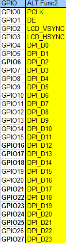
Raspberrypi.org provides this chart showing each pin and its function in DPI mode. GPIO pins 0-3 are always PCLK, DE, VSYNC, and HSYNC. The remaining pins are for the output of the colors Red, Green, and Blue. The configuration of the color pins can change around depending on what DPI mode you choose, but for this guide I’m sticking to the simplest mode that uses all the GPIO pins, RGB24. It’s 24-bit and uses 8 pins for each color (8 x 3 = 24).

Pinout.xyz
The website pinout.xyz gives a better visual of each pin in DPI24 mode. Notice that only the power pins remain.
You’ll also notice that the pins are scattered throughout the 40-pin header.
So what do we do with this information? We need an LCD datasheet to figure that out.
Making the Connections
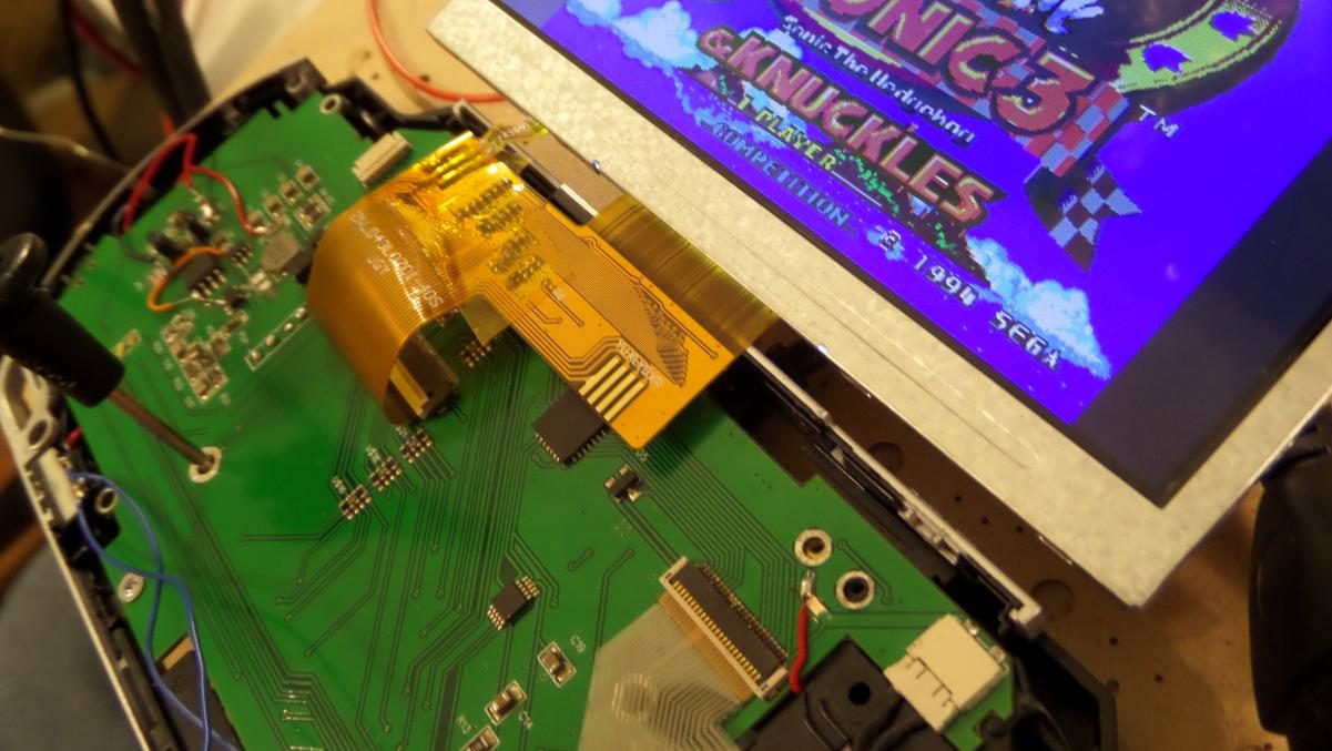
I’ll use an LCD that’s compatible with the new Version 4 board to demonstrate the interface.
It’s a 4.3″ 480×272 40-pin LCD, and can be found here. The image above shows a 40-pin FPC breakout board that gives easy access to the LCD pins (trust me, you don’t want to solder directly to 0.5mm FPC pins), and next to it is the LCD pinout from the LCD datasheet that is available here (on page 7 of 19).
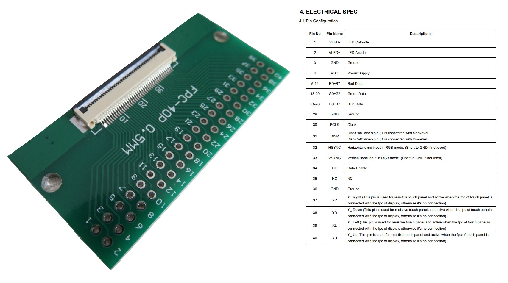
This part isn’t too complicated, just match pins to their function. For example, LCD pins 5 through 12 connect to the Pi’s Red 0 through Red 7 (on the pinout.xyz diagram above). 13 through 20 are for Green. 21 through 28 are for Blue.
Pins 30, 32, 33, and 34 on the LCD are PCLK, HSYNC, VSYNC, and DE, and they connect to CLK (GPIO0, physical pin 27), V-SYNC (GPIO2, physical pin 3), H-SYNC (GPIO3, physical pin 5), and DEN (GPIO1, physical pin 28) on the Raspberry Pi. These 4 pins control all the LCD’s timing.
There’s one pin on this LCD that might confuse slightly, called DISP (LCD pin 31). Don’t confuse it with Data Enable. The DISP pin just enables and disables the entire LCD, and is usually kept connected to VDD.
Pins 1 and 2 on the LCD are for the backlight, and usually get power from a boost converter. Most of these LCDs run at 20-25v and low amperage, but it can vary so datasheets should always be consulted. Some FPC breakout boards, like this one, already have the boost converter built into it.
LCD pins 3, 29, and 36 are all connected to ground. LCD pin 4 gets connected to 3.3v (this also varies by LCD, with some requiring 3.3v, 5v, or a combination of 3.3v and 5v, so check your datasheet). This 3.3v can come directly from one of the Pi’s 3.3v pins, since it’s current draw is low. As said earlier, LCD pin 34 also gets connected to 3.3v.
The remaining LCD pins (37-40) are only used on panels that have a touchscreen on top. They don’t affect the function of the LCD and won’t be discussed in this guide.
But doesn’t it mean, that you can’t use the GPIO Pins for anything else if they are all taken?
It does. DPI24 uses every GPIO pin, so there’s none left to use for other functions. Luckily there’s a couple other DPI modes that leave you with a few remaining pins, and I’ll talk about that in the software part.
Awesome post!
Any chance you’ll publish part 2?
Absolutely. The PSPi board was taking all my focus for the last year, and now I’m shifting focus back to things like this. I’m in the process of setting up for more guides and YouTube content. Hoping to have a regular cadence of posts within the next couple months.
Hello!
Really good entry.
May you give an example of the software configuration?
Thank you in advance
Pingback: Displays We Love Hacking: Parallel RGB | 3d print ......errori ed esperienze,