
PSPi Version 4 Assembly Guide
Updated 5/25/18
Components
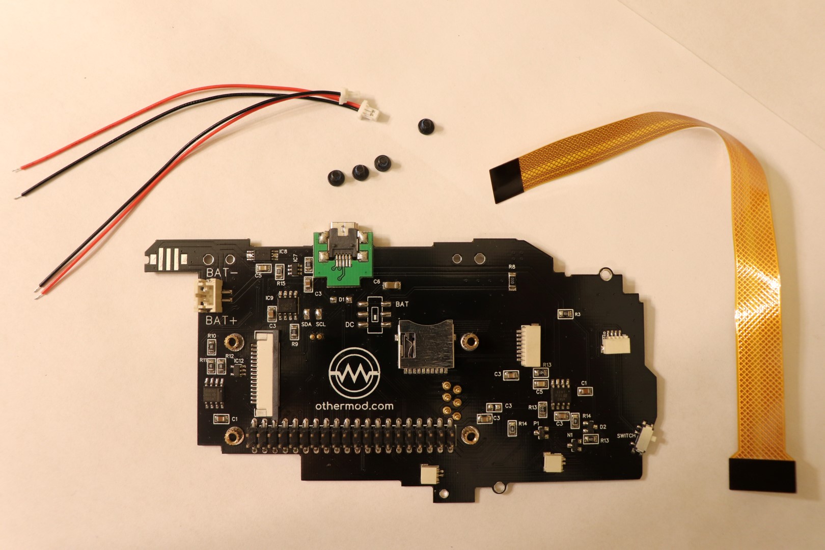
Here’s what you receive in your kit. Board, LCD, wires, and screws.

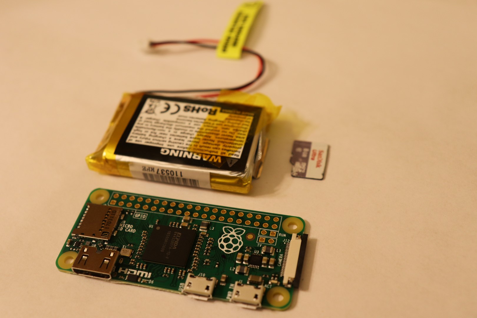
To complete the build, you need the following: Pi Zero or Pi Zero W, battery with JST connector, microSD card, USB to microUSB or USB to miniUSB adapter, PSP charger or USB charging adapter.
The board has a JST PH 2.0mm connector for battery attachment, making it compatible with many available batteries such as the one shown here.

Assembly Process
The CSI cable is shown here. This comes preinstalled in the connector on the board, and must be attached to the Pi Zero.

The cable is somewhat long and needs to be folded underneath the Pi Zero so it’s not in the way. Make sure that the cable does not block the pogo pins next to the microSD card slot.


The Pi Zero can now be mounted to the board using the 4 M2.5 screws.
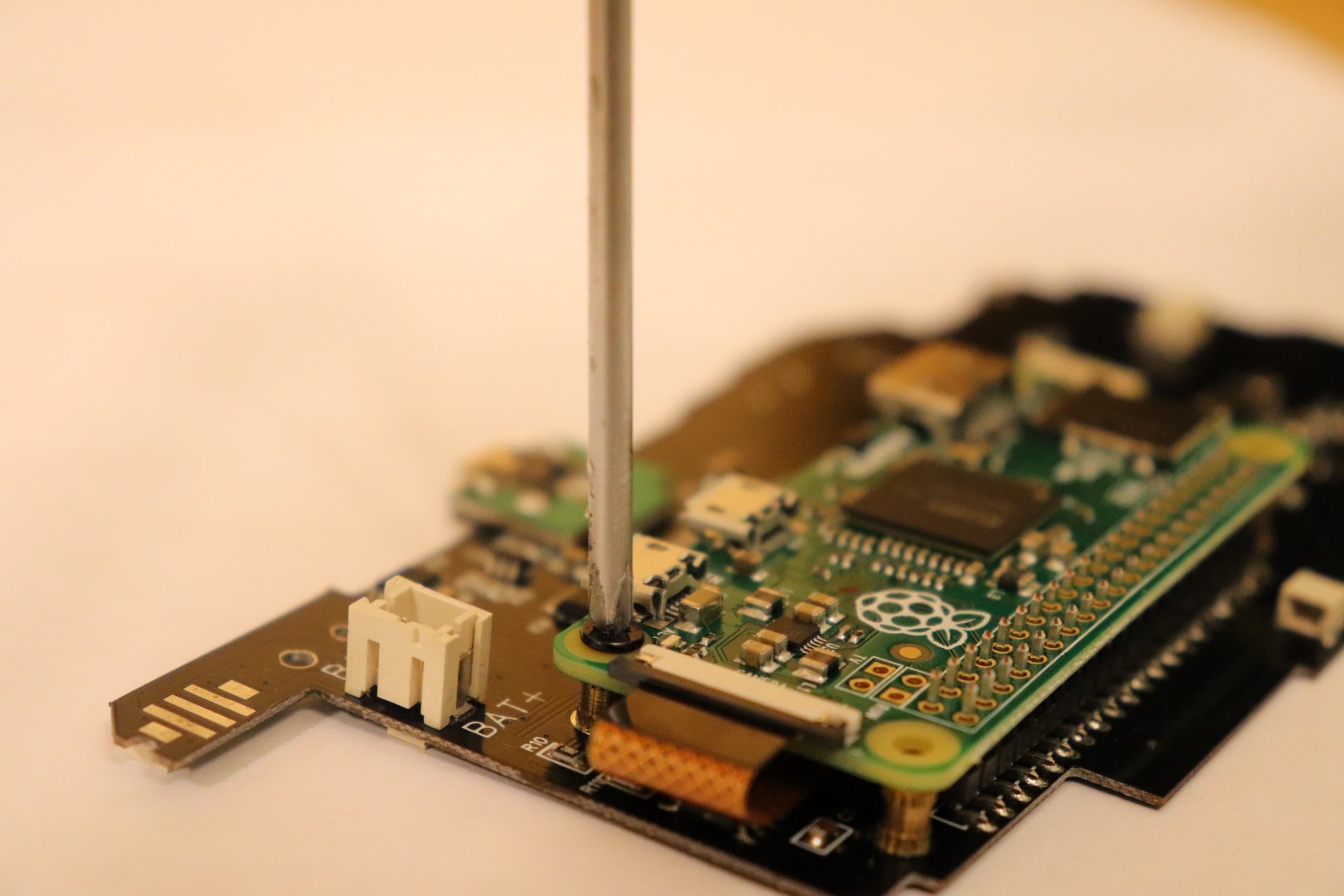

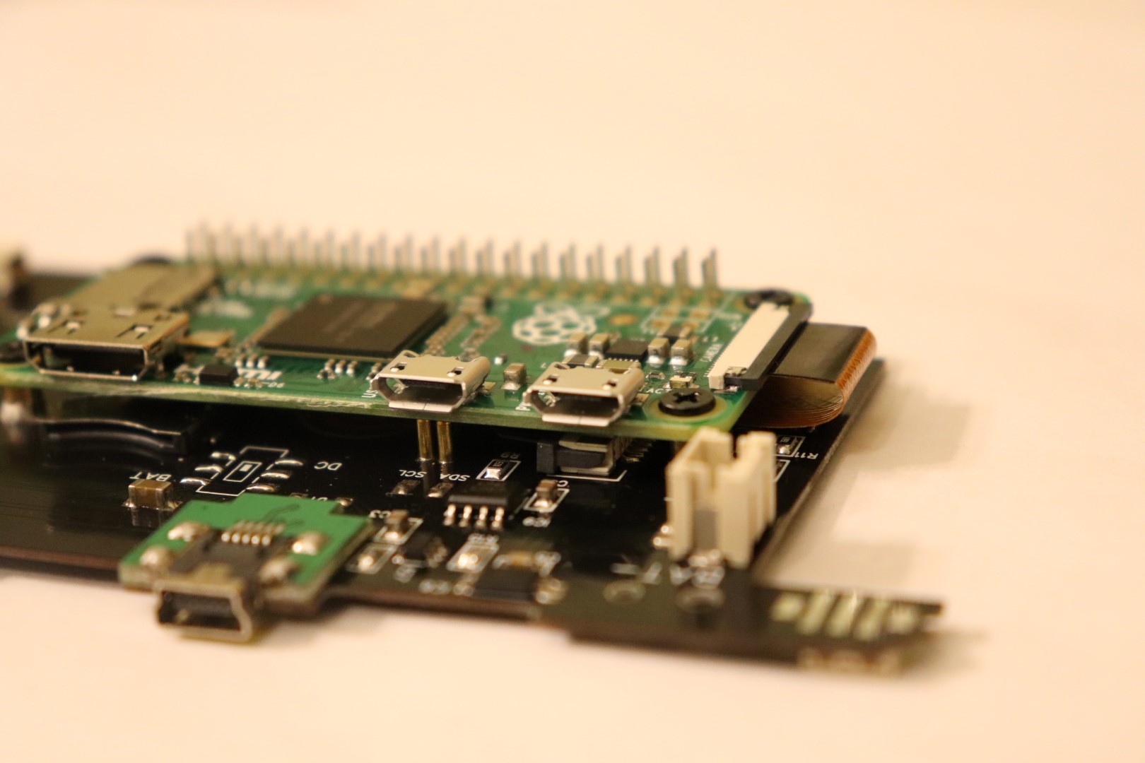
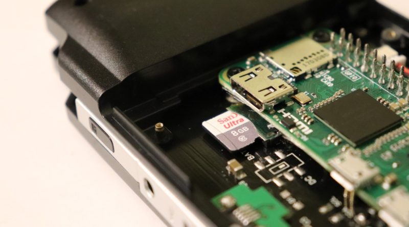
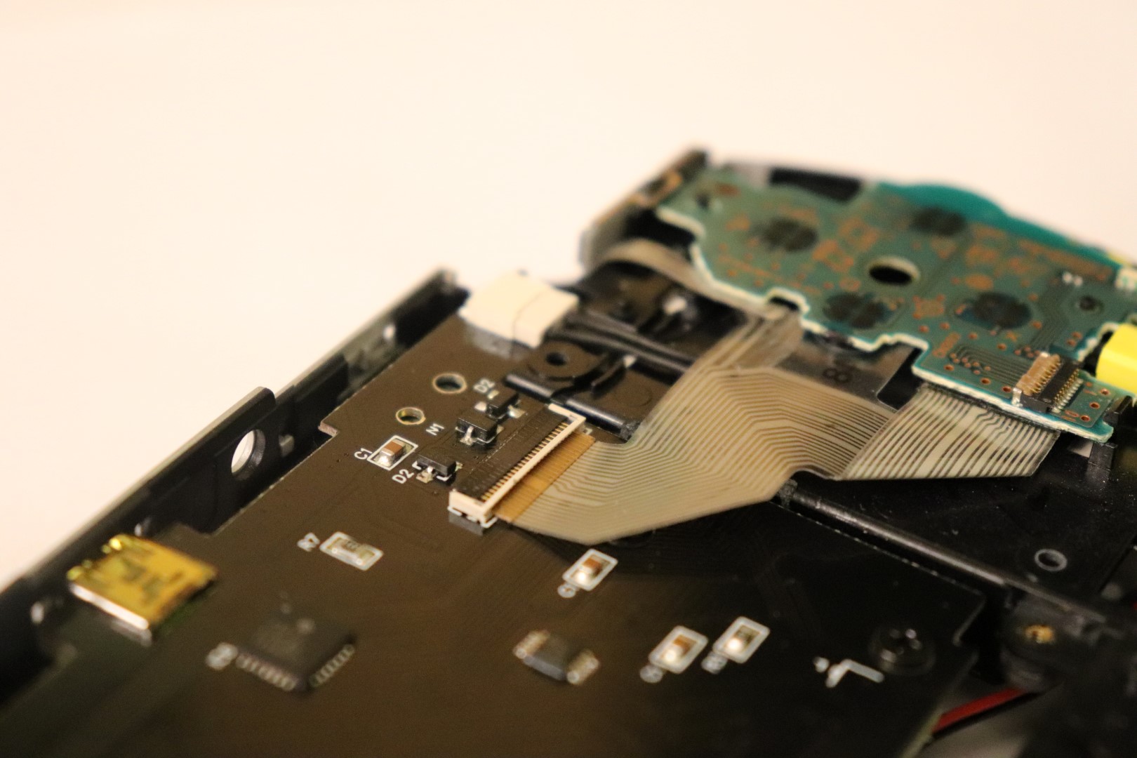
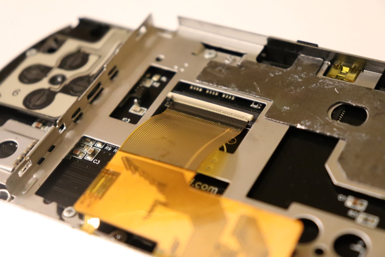
Once the Pi is mounted, the header pins have to be soldered to the holes on the Pi Zero. Before you solder, I recommend checking continuity on the pogo pins. I put the pogo pins on the board so the microSD card can be relocated away from the Pi Zero, making it easier to install and remove the SD card. The pogo pins make contact with the bottom of the Pi, and run to the microSD port that’s positioned above them (shown in the picture below). The traces on the PSPi board then route to an 8-pin JST SH connector, and this connector can be used to verify contact between the pogos and the Pi Zero.
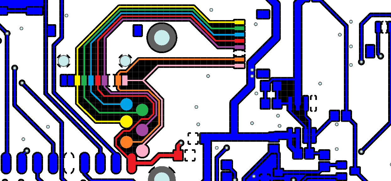
And here’s the Pi with the same colors on the microSD pins. You can use an ohmmeter to check for continuity between the pads on the JST connector and the pins on the Pi’s microSD. That will tell you whether the pogos are making good contact. The 3.3v (red) and GND (white) pins won’t show a connection until those header pins are soldered, so you can’t verify those two yet.

Once the Pi is mounted and checked, go ahead and solder it up.

Disassemble your broken PSP (teardowns are available online, such as this). You should end up with a pile of internal components, and this.

Remove the speakers from the case.
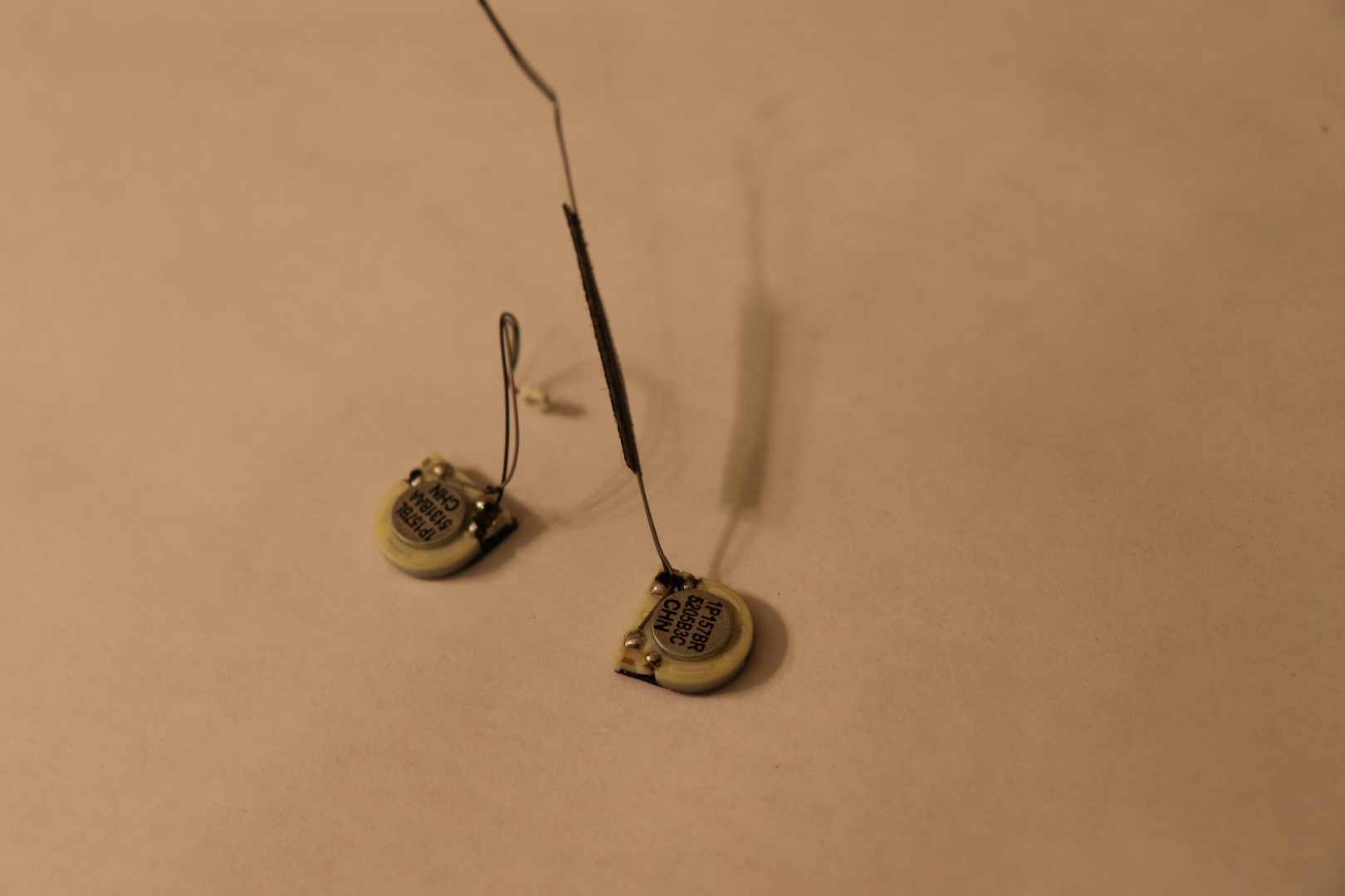
Remove the wires and solder the JST SH wires that were included in the kit.

If you have a newer PCB (1.2), the speaker connection is slightly different. Instead of two 2-pin connectors, there’s only one 4-pin connector. Red and yellow are positive, black and green are negative.

And install them back into the case. I chose to route the right speaker wire through the hole and through the battery compartment. (If you have PCB 1.2 make sure you do the speaker wire routing before you solder the wires to the speakers.

And the left speaker.

Now the plastic shell needs to be slightly modified. This starts with the protruding plastic underneath the 24-pin ribbon cable for the controls.

Cut it flush with the surrounding plastic.
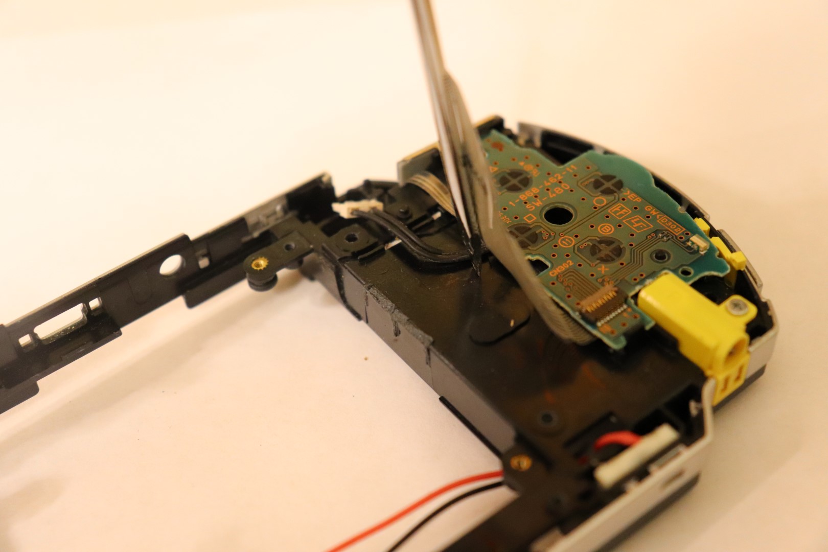
Some pieces need to be removed from the UMD bay as well, near the spring.

Trim these flush as well.

Hook the speakers up to the board and install it into the shell.


Here’s the speaker connector on PCB 1.2

Install the cables. Here’s the power cable that goes into the power connector.


The FPC-24 ribbon

The FPC-10 ribbon


Install the LCD bracket. Loosely install the screws, so the bracket can be adjusted slightly if need be. Check to make sure the conductive joystick pad is still sitting in the LCD bracket. It’s a clear rubber piece with gold pins inside it. Without it, the joystick won’t work.
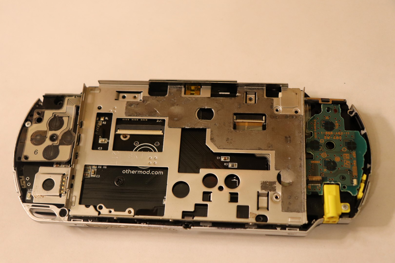
Make sure the small protrusion on the D-pad sits in the notch on the LCD bracket.

Before tightening the screws, position the bracket as shown here. The joystick pads should be approximately centered in the open area on the bracket to prevent short-circuits. Also, if you have PCB 1.1, pay attention to the two small components directly above the bracket. The components have a small white outline, and you should attempt to line the top of the bracket with the white line under the components. These components were relocated in PCB 1.2.
Once you’ve aligned the bracket, tighten the screws.

Install the UMD bay door now if you plan on using the UMD door retention screws. You may need to slightly trim it to help clear the JST connector.
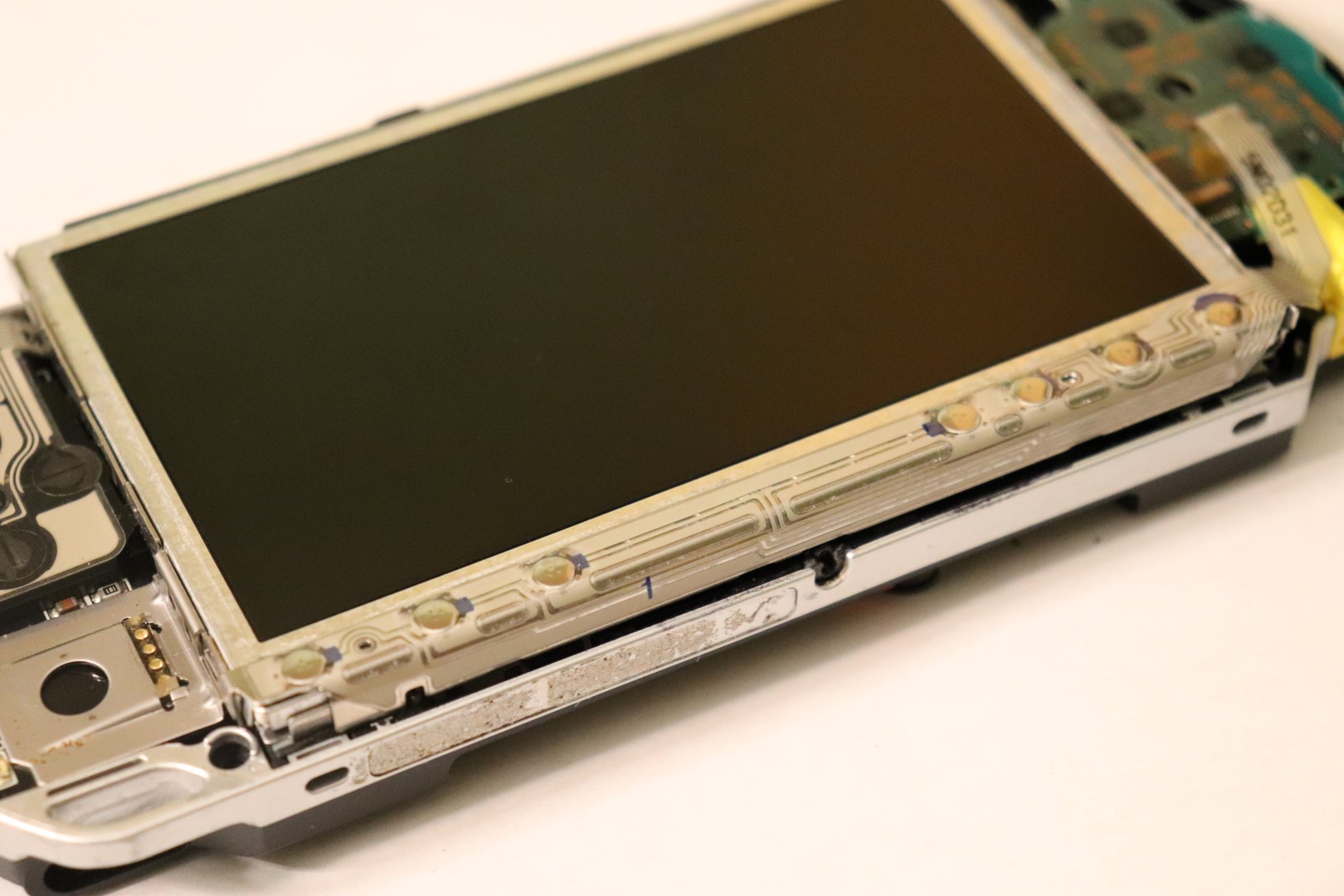
Then install the LCD.


Then install the small control bracket under the LCD

Install the triggers and put the top on the shell, then install all remaining screws.


Install your battery into the battery compartment and attach it to the board’s JST connector. You can route the wire through the notch between the battery compartment and the UMD bay. Make sure your battery has the correct wiring. Some Chinese ones have the right JST connector, but the pins are reversed. Hooking a battery up backwards will probably fry the protection circuits on my board. I put very large letters on the board to show which side is positive (typically the red wire) and negative (typically the black wire).

And install the battery cover.


Software
Option 1 – Use othermod’s PSPi RetroPie image
The image is saved on Google Drive, located here. Download it and use your favorite imaging software (Win32diskimager, Etcher, etc) to copy the image to your SD card. On first boot, it will resize the partition to fill your SD card. No additional software needs to be installed.
Option 2 – Use the RetroPie default image and install the additional software manually
This is written for an offline installation. It assumes that you have a freshly imaged microSD card with RetroPie 4.3 or 4.4.
Start by visiting the othermod Github at https://github.com/othermod/PSPi-1000-Version-4
Download everything by clicking the “Clone or download” button and hitting “Download ZIP”
Once you do that, extract the download using your favorite ZIP file extraction software.

Open the extracted folder, then copy the entire contents to your microSD card. Allow it to overwrite the files on the SD card, such as config.txt. Do not delete any of the original folders on the SD card (especially the overlays folder), just let it merge when it asks.

Install your SD card into the microSD slot on the PSPi board

Attach a USB keyboard (using either the miniUSB connector on the PSPi board or the microUSB connector on the Pi Zero) and power the system on by pushing the power switch upward for a moment.
Once the system boots, press F4 on the keyboard to exit to the command line.
Type the following command and press Enter to install everything:
sudo bash /boot/pspi/setup.sh
It will do a bunch of installations and configurations, then it will reboot after you press a button. After the reboot the configuration is finished and the PSPi is ready to use.


Important Things to Know
The Music button is the hotkey for key combos in RetroPie
The green power LED will turn orange when the battery is needing a charge. This works even when the battery detection code is not running.
Press Music and Square together to enter Retroarch configuration from within a game
The display button will adjust the brightness
Pressing Music and the Volume buttons will adjust the volume up and down
Press the Home button to exit games (works the same as pressing Start + Select or Mute + Select)
The switch on the left side of the case will switch the speakers on and off
Common Questions and Problems
Problem: Volume is too low
Solution 1: From EmulationStation, press Start and go to Sound Settings. Adjust volume higher and try it in a game.
Problem: The board powers on and powers off almost immediately
Solution 1: If the battery indicator is orange, this is most likely happening because the battery is low and safety features are kicking in. Charge the battery for about 15 minutes and try again. You can also just leave the power adapter plugged in.
Solution 2: If solution 1 doesn’t work, the other cause is probably either the microSD card or the software on the microSD card. Make sure you have a freshly imaged version of RetroPie, and that all the files have been copied from the othermod Version 4 Github. Also, to rule out other issues, you can try the microSD card directly in the Pi Zero’s slot.
Problem: The buttons work in Emulation Station, but not in games
Solution 1: Software. If you used this SD card on a previous build, you should either re-image the SD card with a fresh copy of RetroPie or you should wipe all previous controller configurations.
Solution 2: Hardware. If the joystick is not functioning correctly (and this could be because your joystick contact pad is misaligned or missing, or the joystick itself is defective), it can cause this to happen. Retroarch doesn’t respond well when the joystick isn’t centered as a game loads. You can check it by typing jstest /dev/input/js0 into the command prompt and pressing Enter. This will show you a constant readout of the joystick. Wiggle the stick around and the numbers should change. Let go of the stick and the numbers should drop to 0 for both axes. If the numbers don’t change when moving the joystick, then it’s most likely the clear joystick pad that’s to blame, and it’s either missing or incorrectly installed. If the numbers to move but don’t return to 0, it’s probably your joystick that’s to blame. If you get an error that /dev/input/js0 isn’t available, then the joystick software isn’t running.
Question: I don’t need the joystick. How do I disable it so it’s not wasting CPU cycles?
Answer: Edit the file /boot/pspi/boot.sh, and comment out the line for joystick.py (by putting a # to the left of the line). After you reboot, the joystick will be disabled. You can re-enable it later on by removing the #.
Great work! Can’t wait to get started on mine! Eagerly awaiting delivery of my board. I will be sure to come back and share my complete build.
So just checking, does this use the OEM headphone jack as is? Also, any idea of when the board will be done with backorder?
It makes use of the OEM speakers, but not the headphone jack at the moment. There’s a 4-pin JST connector on the board that interfaces with the audio, for you guys that want to solder it up, but my plan is to use the 4-pin connector for a headphone board a little bit later. The headphone board should automatically disable the speakers when headphones are attached, and will possibly have a relocated microSD slot.
What do you mean with “headphone board”. Is it an addition to v4 and will be sold separately? ETA?
I put a 4-pin connector on the board that carries the un-amplified audio signal. I’m working on something that will plug into that connector and bring audio to a headphone jack.
It’s an addition to v4. My focus is on shipping the v4 backorders first (which will take most of my time for the next month), then I’ll work on the headphone board.
Assembling now – the 4 wire speaker connector – which color wire goes to which speaker pole?
Red and yellow are positives, black and green are negatives. The speakers plug into the one labeled SH-4B. I’m posting an update today with pictures for PCB 1.2.
Will the v4 board works with the newer Pi Zero WH (with the already soldered GPIO headers) or is it better to stick to the regular Pi Zero W? Pros and cons?
Also, regarding the headphone board mentioned previously: Does it mean that right now, no headphone will work with the PSPi?
That header would have to come off, so I recommend just going with 1.3 or regular W.
There’s a connector on the board that will give a headphone output if you solder it to the headphone jack, but it will be very low volume non-amplified and unfiltered audio. The board I’m working on will amplify/filter the audio and disable the speakers when headphones are plugged in.
Ugh. All done with the ripping apart and reassembling with pspi board but somehow the connector for the power switch didn’t line up or a piece fell out. Is there anything on the pspi board to short or something to force power on and bypass the switch before I tear the thing apart again and figure out the switch problem?
Woo hoo! Finally got everything working. Not sure if sound is working yet or not. Should it be pwm or speaker in the sound settings? Haven’t found a workaround for the missing power slider piece aside from sliding with a toothpick but need to remove cover to access so not a good solution so far – I’ll scrounge around the table/floor, see if the little piece can be found. Sigh. Another fun thing, wasted a few hours formatting, reformatting, copying, trying to setup the microsd card before realizing I was formatting the boot partition of my surface pro. Should be fun rebooting that later. Anyhow, lesson learned, don’t tinker too late at night!
I’m going to load up some roms and emulators now – I’m assuming if I just follow along on the retropie wiki, I’m good? Mame4all the preferred emulator for mame on the zero?
Quick battery question – I grabbed a 6 pack of 720mah batteries from amazon to tide me over til I get the right ones. Of course they’re a propietary syma connector so it’s off to the rc store for some jst-ph connectors as apparently I don’t have a single electronic or battery that uses the ph version. If I splice 2 or 3 batteries in parallel to bump the mah to 1440 or 2160, any issues foreseen? Should just register as a 1s 3.7v battery to the pspi. Thoughts?
I’ll do a full video of the teardown of my second dead psp1000 and buildout of the second pspi4 mod and post it on youtube. Lego for adults!
Lastly, thanks for putting this neato board out there othermod! This will be a way cool toy for the kids (and who’s kidding, there will be much donkey konging had by dad…).
The default settings for sound should work. I doubt you’ll have to change anything, except maybe the volume level in Emulation Station.
Yeah, retropie wiki methods work. I’m not sure which MAME emulator is the best.
Splicing in parallel (never in series of course) will work as long as they are both 3.7v cells. Just be careful paralleling two batteries that aren’t charged the same amount. One may start to charge the other at a very high rate if they are at different levels. Double-check the pinout on your JST PH connector too, since some of them reverse the pin colors.
Thank you too. I hope you enjoy using it.
Ooh, and in case you’re a tad mentally challenged like me – do make sure you use the right retropie image!! I mistakenly started with the 2/3 version thinking a zero was just a smaller 3 – rtfm would have been smart. That crapped out with illegal operations obviously. Anyhoo – the 0/1 is the image to go with…
Hi i Love your mods Van i also use a PSP 1004?
You can. As long as it’s the original fat PSP 1000 it’ll work.
Is there anyway to add L2 and R2 buttons?
If you’re looking for easily accessible GPIO pins, the two LEDs on the left of the board are probably the easiest things to sacrifice.
Will it be possible to buy the PSPi v4 without the screen since I already have it?
Yeah I can probably do that
Is there a pre-existing bluetooth or wifi option? Or way to add either? For playing games with someone locally? Me and my fiance want to each make one of these and would love to be able to play together.
Sorry i should have read more about pi zero w. I feel stupid now.
If i dont have a psp 1000 can i buy a casing instead ?
Nope, but the used/broken ones aren’t much more expensive on ebay. I bought both, because the unit I bought didn’t look all that great. With a replacement case, you will be missing your ribbon cables, DC charger input (if you’ll be using it), controller pads/contacts, and speakers.
Finally completed assembly of the PSP with your board and gave and issue.
Buttons work in emulation station but not in games.
I verified joystick is functioning properly and tried disabling the joystick also.
Still have issues with Dpad and xyab buttons not working in games.
Using a fresh prebuilt image from your site.
Any suggestions?
If the buttons work in emulationstation you can at least rule out any hardware problems. Drop out of emulationstatation using F4 and make sure every button works. Also, what method did you use to verify the joystick was working, and what method did you use to verify the joystick was disabled?
I figured out the problem. It was an issue with a particular ROM, Super Mario All-Stars, it requires the use of a different emulator that unfortunately runs like garbage on the RasPi Zero.
Jump into retroarch by hitting mute + square after starting the game and set up the inputs for controller 2 instead of controller 1. That should get it working with the default emulator.
Hi there
This things is great!! One thing though, I can’t seen to remap buttons using RetroArch, do you have any ideas why this would be?
Controller works fine, except that A/B and X/Y seem to be switched in ones. I’ve updated all the everything and the RetroArch version I have now is 1.7.3
Oh I figured it out, changed the emulator and it worked ಠ‿ಠ
You can also swap the button mapping in Adafruit retrogame (using retrogame.cfg) if you want to swap buttons.
Anyone know who sells good shells and buttons.. all i see is cheap stuff from china
Hi,
I’ve a problem with the display, the display is showing but quality isn’t good, problem occured after soldering the pi, could this be caused due a bad solder connection? because before it worked fine. If so what pinout do i need to check?
Thanks
Problem solved, issue was solved by cleaning the flat cable of the display,