
Notifications
Clear all
Topic starter
April 8, 2017 8:43 pm
I've finished the kit and I have power to everything but my screen doesn't have an image. Ive reloaded retro pie and the config.txt on my SD card and put it directly into the pi and still nothing. I originally had my Lcd controller board wires switched around, not sure if that could have shorted anything out. And I also damaged the LCD+ connection on my 1000.3 board, got it too hot during soldering and the connecting pad lifted off the board. It still looks connected to the board, just lifted. Not sure if there is a way i could bypass that connection straight to the pi to rule that out. Need help.
thanks

April 10, 2017 1:15 am
The pad being lifted off the board shouldn't be an issue. If the connection is broken, then there are multiple other areas that the LCD power can connect to instead.
Connecting the wires to the LCD incorrectly can be an issue. How bad of an issue depends on what wire was switched. Can you give a picture or description showing what was connected to where?
Do you have a voltmeter available?
Topic starter
April 10, 2017 2:09 pm
Unfortunately I can't remember what was switched cuz i got so excited that it was the problem and switched it back to find out it still wouldn't work. I can say that the wire going from the controller board directly to the Pi was correct. I believe i had the LCD+ and LCD- switched or the LCD+ on the 1 connection that should be empty out of the 4 on the controller board, can't be certain though. I do have a voltmeter though, is there a way to confirm the LCD is still ok?
April 10, 2017 3:14 pm
LCD+ on the connection that should be empty could be bad. That's putting 5v directly to the 3.3v chip.
Put 5v to the black and red connections, and let me know what voltage you get between the black pin and the orange area. The orange area is the other side of inductor 100. You should get 3.3v.
Topic starter
April 10, 2017 3:51 pm
I have it hooked up correctly, turned it on and measured the volts between those two connections you said. I got weird readings, started at 1.0v and slowly trickled down .99, .98 etc. I checked the voltage on the battery to confirm the voltage meter was setup correct and I got a steady 3.6v on the battery, which i think checks out. Doesn't sound good for my screen.
April 10, 2017 3:54 pm
Are you getting 5v at the black/red points?
Topic starter
April 10, 2017 4:51 pm
If you are referring to the red/black points that you highlighted in the picture, no. Im only getting 1-.5v
April 10, 2017 7:22 pm
If you're only getting 1v at the red and black, then something else is going on that has to be fixed first. Those are your power input points. They get 5v from the all-in-one to power the LCD.
Let's start with the basics. With the all-in-one powered off, you should get little to no voltage at the LCD pads. No LED indication lights should be on anywhere. With it powered on, you should get a green or orange LED indication showing that power is on. This LED should stay lit. At this point, you should be getting 5v between LCD+ and LCD-.
Topic starter
April 10, 2017 8:24 pm
I powered it on and checked the voltage between the LCD+ and LCD -. I was still getting the .5-1v from those two connections until i started to push down past the LCD+ onto the board. So from this test I'm pretty confident that the LCD+ connection on the board is damaged. How do I reroute that connection?
Topic starter
April 10, 2017 8:26 pm
Also when I did push down to the board past the LCD+ connection it was reading a nice 5v.
April 10, 2017 8:46 pm
The best option would be to scrape away some of the blue color from the board just below the LCD pad. You can see the outline of the trace where it runs left to right. That whole trace is the +5v line.
The other option is to solder to one of the +5v pins on the Pi. It's the top right pins I colored red. Don't bridge this with any other nearby wires or you'll have a very bad day.
Topic starter
April 10, 2017 9:48 pm
I scraped it away and got it to connect, now have 5v going to the controller board. I still don't have an image.
April 10, 2017 10:02 pm
Now that you've got power going in, check the spot I colored orange before and let me know what voltage you're getting.
Topic starter
April 10, 2017 11:35 pm
I'm getting 3.26v between the orange spot
April 11, 2017 12:37 am
That rules out damage to the built-in buck converter.
So that narrows it down somewhat. Can you post or email some images of your wiring? I want to see if there is anything obvious.
Topic starter
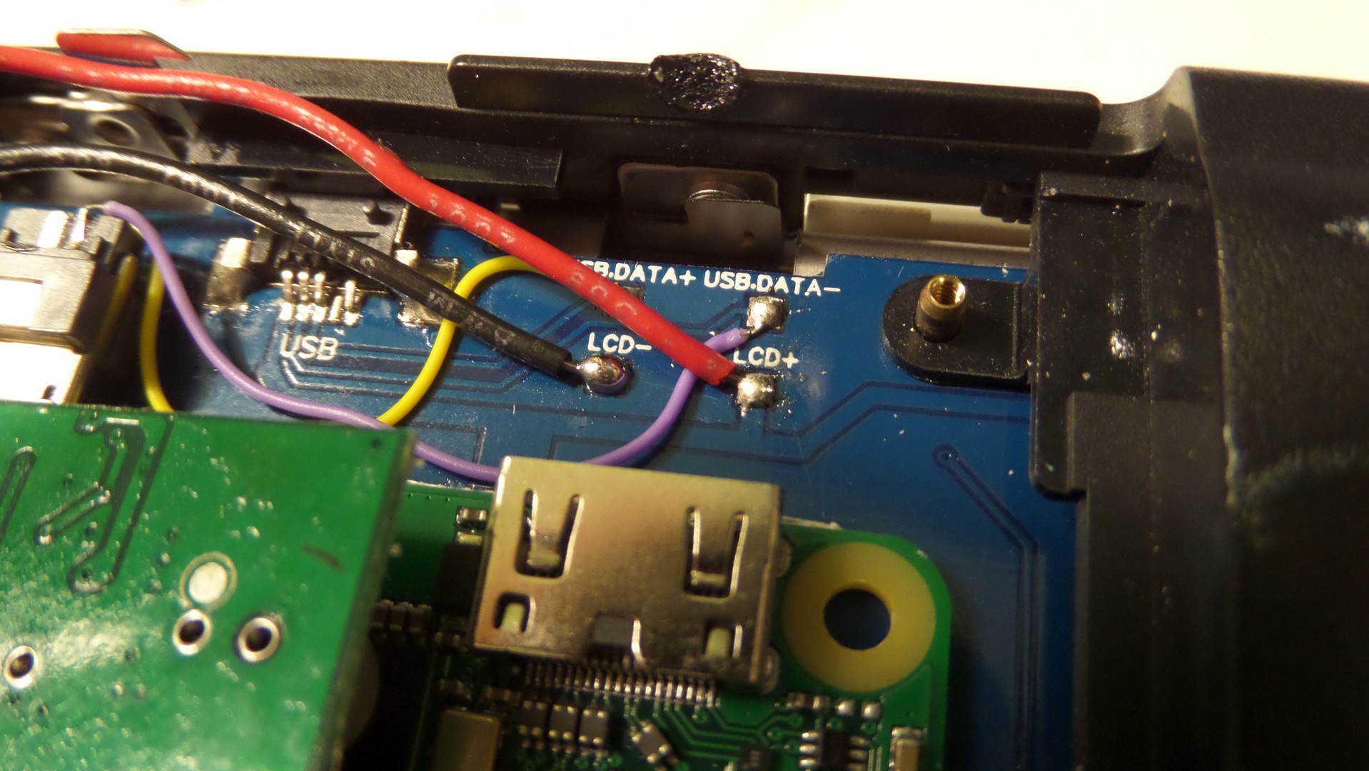
April 11, 2017 1:05 am
April 11, 2017 1:20 am
Everything looks right with the wiring. Do you get an activity light on the Pi Zero after powering it on? There is an LED on it that blinks as it loads the OS. It should blink quite a bit for a minute or so after powering it on.
Topic starter
April 11, 2017 1:46 am
That light blinks twice, flutters for a second and then stays solid. that whole process is maybe 2 seconds long.