
Notifications
Clear all

Topic starter
February 7, 2017 2:15 pm
If you have a composite LCD and you need help getting the board working at 5v, then this is where you will get it.
Also, if you're happy with the help you got, please check out the "Fund the next project" link at the bottom right of my site.
February 10, 2017 11:07 am
Raspberry support 24bit parallel lcd interface by GPIO. Why not use it?
Topic starter
February 10, 2017 1:36 pm
Raspberry support 24bit parallel lcd interface by GPIO. Why not use it?
I am working on it for my own build. It brings other complications, so I haven't decided whether I'll produce a board using it.
February 13, 2017 10:44 am
Topic starter
February 13, 2017 12:31 pm
You lose most of the GPIO, so buttons and possibly audio have to get wired to an external device. If this device is USB, then you lose the USB port. This then means you have to add a USB hub if you want a USB port. Every extra device brings more software configuration and more difficulty.
This is a side project, and I don't have any diagrams yet.
March 7, 2017 4:33 pm
Need help. I messed up my LCD driver board. I removed the XL1509 chip then I asked othermod and he showed me how to wire it but it turns on and off with 1 second interval on 5V.
Topic starter
March 7, 2017 4:42 pm
Do you have a voltmeter to check voltages when it's turning on and off? I'm curious what you're getting between the pad shaded black the top one that's shaded red.
March 8, 2017 7:28 pm
Yes. I checked the voltage and it drops to 3v. I replaced the power supply with a portable battery pack and it worked. Thanks for your help!
March 14, 2017 3:02 am
I'm trying to get this controller board to run at 5v and it is giving me 3.3v at the point that I bleave need to be,before I put 5v to it and fry it can you let me know if you have seen this one before.
Topic starter
March 14, 2017 12:03 pm
I'm trying to get this controller board to run at 5v and it is giving me 3.3v at the point that I bleave need to be,before I put 5v to it and fry it can you let me know if you have seen this one before.
What voltages do you get at the red pads when you attach 5v and 12v to the 12v power input on the board?
March 14, 2017 4:22 pm
At 12v input the top 2 pads get 3v and the leg gets 12v. At 5v input the top 2 pads get 3v and the leg gets 5v.
Topic starter
March 14, 2017 4:30 pm
That's promising. There is a good chance that this will work without any modification. I believe the IC is a variant of the MP2307, so as long as it's getting voltage above 4.75v at the pin and 3.3v at the inductor you checked it should work.
https://cdn-shop.adafruit.com/datasheets/MP2307_r1.9.pdf
March 14, 2017 5:07 pm
Here is the eBay link of the lcd with that board if your interested http://www.ebay.com/itm/321731770337. I will try it at 5v at the 12v input to see if it works and will let you know.
March 14, 2017 6:33 pm
this works great at 5v, just put 5v strait into the 12v input, it also has contrast ,brightness,and resolution adjustments,plus has a second input of needed,it works really good for our project and for the pi zero.if the control board is consistent it would be a very good supply. http://www.ebay.com/itm/321731770337
Topic starter
March 14, 2017 8:56 pm
Excellent. How's the image quality? I'm also curious how much amperage it draws. I've ordered one and can get that information once it arrives if you don't have an ammeter to check it.
March 16, 2017 6:05 pm
The ampmeter that I have is only for ac, once you get it in let me know if it has the same controller board,the lcd is half the thickness as the oem one from the psp,i had to put some spacers not the lcd bracket and had to cut the bracket up a bit to try and get the controller board to fit,it has a awkword mounting position.

March 19, 2017 2:57 pm
I have the same controller board that dlarts has posted here:
http://othermod.com/community/hardware/composite-lcd-controller-boards/#post-232
Is there a buck converter breakout board that anyone knows of that can be used with this controller (5v to 3.3v)? I was going to order the one that othermod sells, but he specifically states it is not meant for modifying LCDs.
Topic starter
March 19, 2017 3:00 pm
Can you edit and re-add the links? I'm adding spam filtering software and it's apparently turned up too high.
March 19, 2017 3:02 pm
I noticed it removed my link right after I posted, and there was no edit option on the post. The edit option is there now, so let me fix it right quick.
Edit: Initial post fixed.
Topic starter
March 19, 2017 4:40 pm
I have the same controller board that dlarts has posted here:
http://othermod.com/community/hardware/composite-lcd-controller-boards/#post-232
Is there a buck converter breakout board that anyone knows of that can be used with this controller (5v to 3.3v)? I was going to order the one that othermod sells, but he specifically states it is not meant for modifying LCDs.
There aren't any that I've found that are small enough to fit into the case. It has to be a very smooth 3.3v or the LCD has a flicker. I've got a newly designed board on the way that does the job really well.
Have you removed any components from your controller board yet?
March 19, 2017 4:56 pm
Not yet. After I noticed my controller didn't have the 1509, I came here to see if anyone else had the same board and seen that dlarts had the exact same one.
Topic starter
March 19, 2017 5:01 pm
Ok hang tight. I'm going to research a couple things and see whether there are is any way to make your's work without a buck converter.
March 19, 2017 5:14 pm
I am in no hurry. This is the display I got to use with the v3 kit that will be here tomorrow. The modified LCD I got from you is for my 2.1 build that I still haven't started on yet. lol
Here is a hi-res pic I took of the board if it helps.
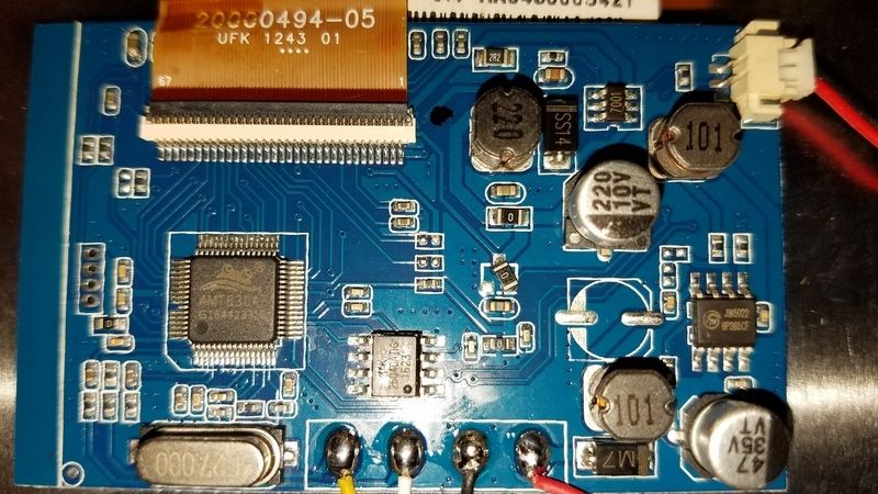
Link to original img. https://drive.google.com/open?id=0BzlmrO_nAlG5X0hnN3lFNzNqVjg
Topic starter
March 19, 2017 7:01 pm
If you get rid of the diode labeled M7 and connect a jumper in it's place the LCD should work. If it doesn't, then the inductor labeled 101 next to diode M7 could be undersized and causing a large voltage drop.
March 20, 2017 9:31 pm
Where do you people learn all this stuff? I wish I knew, its all gibberish in my head 🙁
April 1, 2017 2:53 pm
Following on your guide for V3, can I just splice the power and ground into the power and ground on the controls?
Topic starter
April 1, 2017 3:22 pm
You will definitely fry the board if you do that.
April 1, 2017 3:32 pm
So, use the pads to solder (on the bottom side of the board) as shown in this picture?
Also, is 24awg overkill for the LCD and Batteries?
Thanks for the help!
April 1, 2017 5:18 pm
Yes, those are the pads you want to solder to. As for wiring for power and LCD, I am using 25AWG stranded wire.
April 1, 2017 5:39 pm
Thanks for the response.
I ended up wiring it to the converter.
So far so good
Topic starter
April 1, 2017 6:08 pm
You did exactly right by wiring to the converter. The first few that went out (including your's) were built slightly differently. I've moved to a new design now that's a little easier to work with.
April 1, 2017 6:31 pm
Still need to configure the controls. Right now only the d-pad/directionals work. But I'll get it done!
Thanks again all for your help. The next build will be much easier after this one.
July 7, 2017 6:14 pm
So I soldered the pi up to the LCD board (my board is very similar to the board you have in your modification tutorial) to test if the display works but when I turn on the power the screen remains dark and the power turns off after a few seconds. I measured voltage between the input and ground on the LCD board and it jumps up to roughly 5V before dropping to around 3V. I'm really new to all this so this could be a really simple problem I'm not understanding but any help would be appreciated. Thanks!
Topic starter
July 7, 2017 6:31 pm
I'm happy to help. Can I get some pics showing the LCD controller and how you've got it wired to the Pi?
July 7, 2017 8:29 pm
Dear Sir received your v3 kit about a week ago, great kit! Just getting started on it, this is the LCD board that I have, but I'm not clear if this is the one that is no good or if I'm good to go (on the purchase LCD page it looks like this one but on one of the forum posts I think it was said it couldn't run on 5V). Please advise and thank you for your time.
July 8, 2017 1:48 am
Sorry it took so long. I've removed the wires but the colors show how the wires were connected from the LCD board to the pi
Topic starter
July 8, 2017 1:36 pm
Dear Sir received your v3 kit about a week ago, great kit! Just getting started on it, this is the LCD board that I have, but I'm not clear if this is the one that is no good or if I'm good to go (on the purchase LCD page it looks like this one but on one of the forum posts I think it was said it couldn't run on 5V). Please advise and thank you for your time.
Remove the diode labeled M7 (or just jump across it) and it should work.
Also, where did you get that LCD from? Those are the best, and I can't find them anymore.
Topic starter
July 8, 2017 1:44 pm
Sorry it took so long. I've removed the wires but the colors show how the wires were connected from the LCD board to the pi
Ok so it cuts off because the TX wire coming from the on/off board doesn't appear to be connected to anything. It has to get at least 3v or the board will power everything off. You can connect it to the TX pin on the Pi, or you can connect it to one of the 3.3v pins temporarily so you can do troubleshooting.
Topic starter
July 8, 2017 1:48 pm
Once you do that, I recommend using some 91% rubbing alcohol to clean the board up so you can check for bridged connections.
Also, do you have the ability to hook the Pi to an HDMI display? That will rule out software causes if you get video output to a display.
July 9, 2017 11:51 pm
I hooked the pi up to a display and nothing showed up on screen. Another thing i noticed is that my orange and green light turns on while the pspi charges. not sure if this is important or just cosmetics
July 10, 2017 3:02 am
Sorry for the late reply I was out of town and the forum is not working well on my mobile. I bought this LCD in May before I found your project. It was being sold really cheap on Amazon 13.99 plus a discount code came out to $7. I was hoping to be able to use it in a Pi project, so I got lucky. It was gone for a while but is now back for 19.99. Not sure if they are still using the same board.
Scotabc SC170-02LCM Foldable 4.3 Inch Color LCD
July 22, 2017 1:53 am
I got the recommended LCD and completed the mod but the LCD won't power on.
Any ideas what to check first
Topic starter
July 26, 2017 4:10 pm
I got the recommended LCD and completed the mod but the LCD won't power on.
Any ideas what to check first
Post some pics and I'll see what I can do.
Topic starter
July 26, 2017 4:15 pm
I hooked the pi up to a display and nothing showed up on screen. Another thing i noticed is that my orange and green light turns on while the pspi charges. not sure if this is important or just cosmetics
Hey Kevin I was making some forum fixes and it looks like your reply got stuck in moderation. If you arent getting anything from HDMI then that's pointing to a different issue, I'd say either with the Pi itself or with the SD card or image.
The green and orange lights aren't anything to worry about at the moment. It probably means something isn't hooked up entirely, but it won't cause this type of issue.
July 28, 2017 12:40 am
I got a new LCD can you just confirm what components I should remove.
July 28, 2017 2:18 am
The LCD seems to run with a 5v power supply as is. Do I need to do the mod on this driver.
Topic starter
July 28, 2017 3:47 pm
The LCD seems to run with a 5v power supply as is. Do I need to do the mod on this driver.
What is written on the 8-pin chip? It appears to be a variant of the 1509
August 15, 2017 6:25 am
Hey.
I have 2 of these boards.. and i tried a few things to get them to work woth 5v.
but i am in need of help.
Board:
The IC in the cirkle is a TD1519A
(2A 32V Synchronous Rectified Step-Down Converter)
And here is a link to it`s datasheet:
http://www.datasheetspdf.com/PDF/TD1519A/1006487/1
I tried following othermod`s LCD Guide. and have tried the following:
Tried running it with 5v directly: Did not work.
Tried running 5 v via the 3,3v connection at the bottom left ( you can see the cable in the picture) It did work. but the board got really hot.
After reading up on the guide i found that the datasheet. and this on page 9
so i tried to remove the IC TD1519A and the inductor L1, and running 5v direct to the output.. but the screen does not turn on.
Any surguesstion?
Topic starter
August 15, 2017 10:10 am
Is the other one modified yet? If not, try removing the diode labeled M7 and putting a jumper in it's place.
August 15, 2017 10:37 am
No the other one is new not used or modified.. I will try it later today and post a reply here.
August 15, 2017 11:41 am
I have some bad luck with these driver boards.. =P
I tried to remove diode M7, and put a wire-jumper between the pads.. but no change.. still pitch black and no image.
I still have the the option to solder it back. if you have any other ideas?
August 15, 2017 11:41 am
I have some bad luck with these driver boards.. =P
I tried to remove diode M7, and put a wire-jumper between the pads.. but no change.. still pitch black and no image.
I still have the the option to solder it back. if you have any other ideas?
Topic starter
August 15, 2017 12:15 pm
Ok keep it the way it is for now and let's check one more thing. There is an inductor labeled 331 next to the jumper. When you have 5v applied to the board, can you check the voltage at both sides of the inductor?
August 15, 2017 12:45 pm
It is 5.21v one one side. And 5.17 on the other side.
August 15, 2017 1:15 pm
On the td1519a ic i get:
Pin 2: 5v
Pin 3: 3,3 v
Pin 7: 5v
But no picture om the lcd
Topic starter
August 15, 2017 11:15 pm
Are you getting 3.3v on both sides of the inductor labeled 470?
August 16, 2017 6:37 am
Thanks alot for the help so far.
Yes. It is 3.3v on both sides og that inductor.
Topic starter
August 16, 2017 1:30 pm
That covers all the power input. It's definitely doing it's job and dropping voltage to 3.3v for the main IC to use. There's something else going on here causing the problem.
Are you able to check the composite video signal with another LCD? Also, the FPC cable in the image looks unlike any LCD cable I've seen. Are you using an extention cable?
August 16, 2017 6:14 pm
I dont doubt you.. but i did some testing and here is the current status.
I am unluckey wiht the driver boards.. ;P but the removal og the diode is not the correct fix for this board.
I was successfully running the lcd initialy from giving 5v via the 3.3v input. But the board gets hot (not broken) That was why i wanted a better conversion og the driver board.
The video signal i use is from the pi attached to the v3 board.
But i use a secend screen for testing. That is the ribbon you see. Works well. And it is cross checked with my Nintendo NES system. So i know it work..
So i soldered on the diode back on the board and connected to the nes And my lab-power station..
Result was as expected. No picture at 5v.. but if i up it to 10,5 v i get picture..(it is designed for 12 v) so noting is broken on the driver board. And the video signal is good. :/
So conclution is that the board does not function well on 5v. 🤔
Where can i get a decent pair of boards? (Screens with boards?)
Topic starter
August 16, 2017 6:46 pm
Can you post a pic of the bottom side of the board?
August 16, 2017 7:28 pm
Here it is.
Dont look at the solder wires.. ;P it's just for the testing.. looks slit cleaner When i an not just testing. 🙂
August 18, 2017 11:44 am
I found another driver board..
If you want to give some input, I will try to get this one to work instead..
here is picture front and back
August 21, 2017 4:22 pm
Do you think ut is possible to get this to work on 5v?
Topic starter
August 21, 2017 11:03 pm
I am trying to find a dtasheet for the AS269 IC. Can you attach 12v to the board and tell me what voltage you get at the pins of the IC, and tell me what voltage you get at inductor 470?
August 22, 2017 11:48 am
I will try to messure.. but i think the ic is A5269 instead of AS269.. should be easier to get a datasheet now 😉
August 22, 2017 11:57 am
At 12v input..
At pin nr 2 I get 11.2v
Pin 3 i get 3.3v
And at inductor i get 3.3v
Topic starter
August 22, 2017 3:33 pm
Ok this is the standard MP3302-style chip used in most of these boards.
It can do 4.75v-28v in and drops it straight to 3.3v. If you put 5v to the board, then the voltage drop across the diode (M7) will put you at 4.2v or so, and the board won't work.
To get it working, you just need to do exactly what I recommended on the other one. Either short across M7 or remove it completely and put a jumper. That will give you 5v at the chip (give or take a little because of input inductor resistance), and it will output 3.3v to the main IC. Make sure you do not put 5v directly to Pin 3 or you'll kill everything, just put 5v at the normal 12v input pads. The only thing you lose by removing the diode is the reverse polarity protection, so just don't hook it up backwards.
August 25, 2017 11:50 am
Hi.
you are correct that the chip works with 4.75v-28v. and that it drops down to 3.3.
but something is off.. I use a adjustable labaratory power supply. so i adjust to 5v. and i get a picture that rolls over the lcd display.. if i input alittle more voltage it gets steady. but i do not have that option on the PSP.. i have tried another new board. with the same chip.. removed the M7 Diode.. and got the same result..
can i input 5v direct to the A5269 and get it to work that way?
Topic starter
August 25, 2017 1:02 pm
I've tested this same type of IC down to 4.9v without issues. It's possible that you're getting a large voltage drop across the first inductor, labeled 221. If it has high resistance, then it could be dropping your voltage below the minimum for the chip input. It does appear to be slightly small, so it could be amperage-limited. You can bypass it and attach directly to the input of the IC. You will lose some of the filtering, so the LCD image might suffer slightly.
Can you get a voltage measurement on both sides of 221 with 5v at on the board? I'm curious how large the voltage drop is.
August 25, 2017 4:47 pm
Hi. Good that means that it is hope. 😉
With a input voltage of 5.09volts i get 4,88v on one side og the inductor 221, and 4,74v on the other side.
Seems to be like you say a drop. Sunde the screen is blinking and flickering across the lcd.
Topic starter
August 25, 2017 5:23 pm
Wait, those numbers aren't making sense. That inductor should be connected directly to 5.09v on one side. Is the diode M7 still installed on this one?
August 25, 2017 7:33 pm
No the m7 diode is removed and replaced with a jumper. (Piece of cable).
Topic starter
August 25, 2017 9:12 pm
That's what I expect should be the power path, just judging from component placement. Everything red will get the full 5.09v. There are no components on that path, just traces. The voltage drop should only occur after the inductor, shown in orange. Are you positive your supply is actually outputting 5.09v? If so, you should be getting 5.09v at the input, at both sides of the diode pads, and at one side of the inductor.
August 27, 2017 6:23 am
now we are getting somewhere. =D
Yes i am positive the board had 5.09v. I messured the the output of the power supply. see pic..
and as the messuring result i provided on both sides of the inductor was also correct. =P
BUT.. as i know have 2-3 board that operated the same way, i messured the 5.09v input.. on the board and got only 4.9v.. so i think i know found the misstake i made.. and it is the supply test cable from the power supply to the driver board.
it is abit long, so the resistens in the cable drops the voltage down from 5.09 to 4,9 volts
August 28, 2017 5:57 pm
So I got my board from here but I'm a bit uncertain about wireing it up.
Is my mock correct?
So
- red to bat+
- black to bat-
- green to ground
is that correct?
I saw some posts soldered four wires. Why this?
Greetings
Rob
Topic starter
August 28, 2017 6:53 pm
That is incorrect. Hopefully you haven't supplied power to it yet.
There are 4 pads. The pad above the one you colored red is the one that should actually be red. You have both the red and black shifted down, and they both need to be shifted up one pad.
Also, the LCDs run off 5v, so attaching them to BAT+/- will not work. They have to be soldered to a 5v power source. If you're using this for a v3 build, then the correct pads are LCD +/-
Topic starter
August 28, 2017 6:54 pm
And green attaches to the composite video source, not GND
August 28, 2017 7:38 pm
hey, of course I waited for a response 😉 🙂
so just to be sure (better ask three times than fail hard one time)
So of course I meant LCD+ and LCD- with Bat+&Bat-
Again:
- green to ground
- red to lcd+
- black to lcd-
(like in the v3 tutorial)
greetings
Rob
Topic starter
August 28, 2017 9:06 pm
All good, except green. It doesn't go to GND, it goes to the composite pin on the Pi Zero
August 31, 2017 6:09 pm
I am having trouble with this one. Any help will be appreciated. Apologies if this board is common.
Topic starter
August 31, 2017 8:08 pm
Are there any numbers on the 8-pin IC at the bottom? Do you have a voltmeter?
August 31, 2017 11:04 pm
I do have a voltmeter and the number on the bottom IC is TD1519A.
Topic starter
September 4, 2017 3:45 am
Looks like you can get it working by shorting across the diode M7. That will increase the voltage going into the IC enough to get it working at 5v
September 5, 2017 1:37 pm
Okay. I removed the diode and jumped it and the lcd is just flashing white on and off randomly. I'm thinking it could have something to with the lcd connector but I'm not too sure.
Topic starter
September 5, 2017 2:01 pm
Can you verify that your putting at least 5v into the LCD power input? If it's under 5v then the IC won't function correctly.
September 5, 2017 2:12 pm
Yeah. I have a load soldered directly on the input for 5v. I also measured the pad on the board to confirm and it's coming out to a little over 5v. Could it be a bad IC? Maybe something shorted it out after I opened it.
Edit: Just measured the pin on the lcd connector's vcc and it's 3.3v.
Topic starter
September 5, 2017 3:44 pm
3,3v is what you want, so it's at least working partially.
There's one more thing to check. With the board powered on check the voltage at both sides of inductor 331. If it's a low-amperage inductor it could be dropping your voltage too low.
September 5, 2017 3:53 pm
Getting 5.2v on one side and 5.23 on the other.
Topic starter
September 5, 2017 9:27 pm
Those numbers are exactly what I'd expect. It should be working. Have you tested the composite signal on anything else?
September 5, 2017 10:03 pm
I ran it on a two pi's (one previously hooked up to another driver) so I don't think that is the issue. I put the m7 diode back on and tried running it at 12v just to see if it did the same thing and it does. I'm starting to think it's the lcd connector itself or something else on the board is messed up.
Anyway, thank you so much. You were a big help.
Edit: I replaced the connector and now it's working fine. So all in all, it was just jumping that diode. Again, thank you for the help.
November 17, 2017 8:43 pm
I've managed to get this working using this screen:
https://www.amazon.co.uk/gp/product/B016ZUBQN8/ref=oh_aui_detailpage_o02_s00?ie=UTF8&psc=1
I followed the guides in the other thread. I'm being a bit reckless and haven't much practice soldering...but having a lot of fun thanks to this site!
I left what I understand is the buck converter on. I don't really have the equipment to remove it. What's the downside to this?
The screen's a bit fuzzy but other than that it seems to work great given the price.
February 19, 2018 10:15 am
has anyone seen this control board and gotten it to work at 5v?
Topic starter
February 19, 2018 4:15 pm
snap a picture of the bottom and I'll see what I can do to help
February 26, 2018 7:49 am
i still cant seem to get my screen working at 5v
Topic starter
February 26, 2018 2:06 pm
It appears to be a 3.3v buck converter, and the large voltage drop across the diode (appears to be labeled M1) is probably keeping it from working (it needs 4.5v to work). Bypass that diode and you should be up and running.
If that doesn't do the trick, it's also possible that the inductor labeled 221 is low amperage and is also reducing voltage. Take voltage measurements on both sides and let me know how much the voltage drops.
February 27, 2018 5:59 am
thank you,i got it going,bypassing the diode worked,the controller board draws more power then i like,but ill find a work around.
March 22, 2018 5:34 pm
Hi I just got a new LCD and I don’t know what to do to make it work at 5v. On the picture you can see I have tried to replace the diode with a (green) cable but this didn’t change anything. The screen is white and is sometimes blinking when powered on. Also this came with a red wire soldered to the board. Could you help me please ?
Topic starter
March 22, 2018 8:13 pm
Looks like you have the XL1509 buck converter. It drops voltage to 5v instead of 3.3v. Are you able to remove that IC entirely?
Also, it looks like you hit a few surrounding components when soldering that wire. I recommend cleaning that up.
March 23, 2018 10:03 am
Thanks for the response. Yes I managed to remove the XL 1509 buck converter. Now should I remove anyting else ?
Yes you are right. I tried my best to clean that up.
Topic starter
March 23, 2018 11:35 am
It's 50/50 on whether you'll ahve to do more, just depends on the amp rating on the input inductor.
Check this out
You want to solder the VIN and OUTPUT pads together. Should be pretty easy to identify them, because all the pins on the opposite side are connected to ground. Once you do that, give it a test. If the board still doesn't work you'll have to check the voltage at those two pads. It should be in the neighborhood of 5v.
Page 1 / 2
Next