
Analog/Digital I2C Gamepad on RetroPie
February 20, 2022
This guide got a major update, and is getting a re-release. It now adds the MCP23017 for a fully-functioning gamepad with analog joystick and buttons. The new code is live on Github.
This guide requires two items:
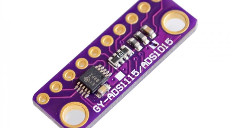
ADS1015 I2C Analog Module
MCP23017 I2C GPIO Module
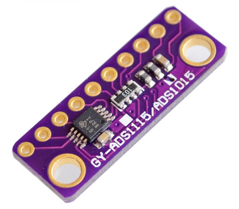
ADS1015 Analog to Digital Expander 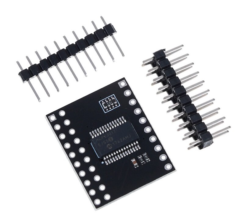
MCP23017 GPIO Expander
Hello.
Could it be used in I2C1 port? I want to test it with Pi 3 connecting to gpio and I would like to use this port instead I2C0.
Short answer is yes. Long answer is that I’d need to update the tutorial to show how it’s done, and that might take a bit.
Ok, I can wait.
I know that you are too busy assembling PCBs
After 3 years have you done it ;D? I am working on a project, and my current setup uses I2C1 (physical pin 3 and 5). Could you please give atleast a crude explanation as to what to do? I really need to get this working.
Thanks.
Lets make it an even 4 years. The driver got some updates and changes, and the new code is on GitHub. I’m updating the guide.
Hi I seam to be missing something. Where do you copy the files to on the SD card?
Hi, after sudo python joystick.py & the Pi give me an error on file joystick.py line 50. IO error no file or directory /Sys/class/humon/humon0/device/im4_input. I double checked my wiring and is ok. It seems like my I2C doesn’t communicate. Could you please help me with this? many thanks!
This guide is very outdated, and the overlays don’t work the same as they used to. I think I can set some time aside to update it.
it will be great! losing my health making it works!
thanks
The code is updated and got some changes to add a GPIO expander. I’ll update the guide shortly.
Thanks!!! looking forward for the guide.
Hi! I tried the recent feb22 version of the library. It works perfectly with the mcp23017, and detects 1 out of 4 channels of the ads1015 module. I tried a lot of things including editing gamepad.c and changing number of joysticks to two (that was the last resort). The multiplexing isn’t working as expected. It is totally possible that I’m using an ads1115 but the module looks the same as shown here. Maybe a bug?
I’ll double check the code when I get a spare few minutes.
I recommend checking the marking on the IC and compare with page 41 of this PDF https://www.ti.com/lit/ds/symlink/ads1015.pdf
I checked everything again, and it all works fine. The issue is probably with your module.
Hi! Thanks for looking into this. I took your advice and checked the package markings. It seems I have an ads1115 (BOGI). I’ll try to tweak your library to see if i can make it work. Please let me know if there is a known workaround. In any case, thanks for the great work, the mcp23017 works perfectly and lets me game a bit on the pi 😊
Assuming all the registers operate in the same manner between the chips, it’s possible that only one line needs to be changed. Line 180 in the current driver is where the math happens to convert the reading to a voltage.
https://github.com/othermod/Analog-Digital-I2C-Gamepad-on-Linux/blob/6d61b0b71c771f5025e07a187659168727490429/gamepad.c#L180
Try changing this:
ADCstore[input] = (((ADS1015readBuffer[0] << 8) | ((ADS1015readBuffer[1] & 0xff))) >> 4) * 3;To this:
ADCstore[input] = (((ADS1015readBuffer[0] << 8) | ((ADS1015readBuffer[1] & 0xff)))) * 3;I only did a quick reading of the datasheet, and more changes might be needed, but this is a good thing to try first. Try it and recompile the code, and let me know whether it works
Ummmm which variable do I tweak to set bits 7-5 of the config register?
Unfortunately that didn’t work. I tried (with and without) changing the calibration values but that didn’t help either. Only one channel responds. Afaik the sampling rate is much lower than the ads1015 (something like 860sps) so that might be a thing (will try continuous mode 2 tonight). I’ve worked with ads1115 once before for an arduino project, but my understanding of bit shift is poor.
Can you create a topic in the forum? http://othermod.com/forum/support-for-external-projects/
I’m happy to continue helping, but this chat is going to fill the comment section, and the forum is the best place for it.
I think you’re right about the sampling rate. I’ll point you in the right direction once I have a little more time to read the datasheet.