
Raspberry Pi Zero Audio Circuit
This guide was updated on 2/8/17
Background
There are a few ways to get audio from the Pi Zero. The easiest is just to use an HDMI display, but that’s not always an option. The next option is to use a USB audio adapter. That works fine, but takes up the only available USB port unless you have room in your project for a microUSB hub. There is also I2S over GPIO, but that requires some software tweaks that make it a little more complicated (a guide is coming for it later this year) There is a another option, and this guide explains the the process of getting PWM audio working.
The Process
The Raspberry Pi is able to create audio using a pair of GPIO pins. The problem is that the audio is badly distorted. The low notes are too low and cause the speaker to rumble and sound blown, and the high notes have lots of unwanted noise. To assist with removing these noises, this audio filter circuit was added to the original Raspberry Pi.
An audio filter serves to remove unwanted frequencies. A low-pass filter removes high frequencies, and a high-pass filter removes low frequencies. The names say it all.

Here is an image to help visualize the process. The Pass Band is the range of frequencies you want to reach your speaker, and you want everything else removed. The HPF (high-pass filter) in this image is removing most of the frequencies under 100Hz. The LPF (low-pass filter) is doing the same for frequencies above 5kHz.
[spacer height=”1px”]
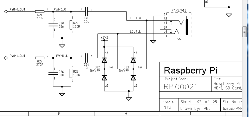
The filters in the original Raspberry Pi did the exact same thing. The schematic above shows both PWM audio channels, so let’s trim everything down and look at just one of them.
The PWM0_OUT is the unfiltered audio signal, and this comes directly from GPIO pin 13 or GPIO pin 18 (one for left audio and one for right audio). Since I’m showing the right side only, let’s say that this is coming from GPIO pin 13.[spacer height=”1px”]

Now we know that PWM0_OUT is coming from GPIO pin 13, so let’s move further into the schematic. We immediately get to the first part of the circuit, which is the low-pass filter.[spacer height=”1px”]
 Here is a Low-Pass Filter (link to Wikipedia) for visualization. Our’s consists of a 270 Ohm Resistor connected in line, followed by a 33nF Capacitor connected to ground. The ground is any negative pin or connection on the Pi Zero. The high frequencies are now filtered out.
[spacer height=”1px”]

Moving further into the circuit, we get to the high-pass filter.
[spacer height=”1px”]
 Here is a High Pass Filter (Wikipedia). Our’s consists of a 10uF Capacitor connected in line, followed by a 150 Ohm Resistor connected to ground. The low frequencies are now filtered out. You might notice that the capacitor in this filter is positioned before the resistor, so that’s exactly what we are going to do with our’s.[spacer height=”1px”]

Here is the modified schematic that makes this a correct high-pass filter. The capacitor is now positioned before the resistor.
[spacer height=”1px”]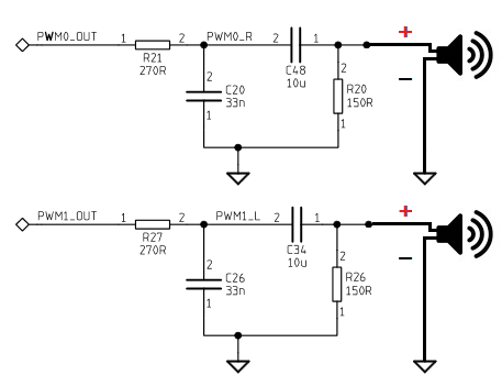
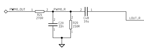
That completes the right side, and now we have to do the same for the left side. Instead of connecting to GPIO pin 13, the left channel starts from GPIO pin 18. Once the left and right channel filters are built, you will have working audio. Connect the filtered audio to the positive side of the speaker, and connect GND to the negative side. Again, this can be any GND connection from the Pi.
[spacer height=”1px”]
We aren’t done yet though. The audio coming from the PWM is very weak, and it’s made weaker by passing it through the filter. This is plenty if you only need to power headphones, but it really isn’t enough to power speakers. We need an amplifier if we plan to do that.
 This amplifier is perfect for the Raspberry Pi. It’s small and packs a lot of power. It works from the same 5v that powers the Pi, and has the perfect design for PWM audio. Best of all, it’s cheap.
[spacer height=”1px”]
 The yellow L and R pads on the amplifier are the positive left and right PWM audio inputs. Between them is a shared ground input, which can be any of the grounds on the Pi. The red pad is the 5v power input, which should come directly from the Pi’s power source. The orange and blue pads on the right are the audio output leading to the speakers.[spacer height=”1px”]
[spacer height=”1px”]
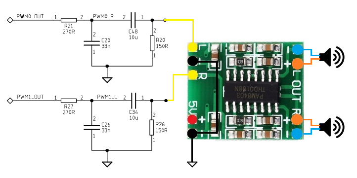
There is one final detail related to the hardware that needs to be covered. The PWM audio is good, but it does have one drawback. There is some unwanted noise on the PWM line, even when using the filter, and the amplifier amplifies this noise as well. There is a pretty simple method we can use to minimize it though.
The noise on the PWM line is constant, and it doesn’t increase as you increase the volume of the operating system. To use this to our advantage, we start by increasing the operating system volume to the maximum 100% volume. This creates an audio output from the amplifier that is incredibly loud. Now that we have an output that is too loud, but we can limit it using one more trick.
 [spacer height=”1px”]This final image shows that trick. A resistor has been added to each of the speaker outputs. I’ve labeled it as 100 Ohm, but anything from 100 Ohm to 200 Ohm works well, and you may prefer something different depending on the volume level you need. Increasing the resistor will lower the volume, and that will also lower the amount of noise you get from the PWM.
That covers the hardware portion, so let’s move to the software.
Software
The last part of the process is telling the Pi Zero to use PWM for audio. This part is very simple. All that’s required is that you add one line of code to the bottom of your config.txt file on your SD card:
dtoverlay=pwm-2chan,pin=18,func=2,pin2=13,func2=4
What to Purchase
The audio filter on a small PCB is available here.
The audio amplifier is available here.
To simplify the process and purchase the improved audio amplifier that has the audio filter already integrated, visit the store page here.
Hey,
Awesome build you made!
I also want to build my System in a PSP 1000 and was hoping you could help me out:
I plan to use a USB Soundcard in my Build, a Model with Buttons to turn up/down the Volume and mute the Sound i should ad.
The main Reason for my plans are this Buttons. I would like to use the Buttons “under” the Display to control it… Should be possible if i re-route the FCB Cable to it, they are simple Tactile Buttons…
My Question ist: What do i need to use if i go this way?
I Would gues the the High an Low Pass Filters are not needed anymore because the USB-Board takes Care of that?
Should i even skip the Amplifier?
Help would be Awesome!
If the buttons for volume up/down operate by connecting to ground, then yes that should work fine.
The filter and audio amplifier shouldn’t be needed if you’re using a USB sound card.
Which USB sound card are you using?
I have one lying around and a cheap one from China should arive soon.
The expensive one is linked under my post.
The comments say it should word fine with Linux and a Pi 2. I didnt have time yet to test it myself…
Well, then i will try to finde some Time to test it Out… i have Speakers and a 5 Pin 3,5-jack Around…
Oh i forgot the Link -.-
https://www.amazon.de/CSL-Soundkarte-Dynamic-Surround-Funktionstasten/dp/B00BBCXVG6/ref=sr_1_3?s=ce-de&ie=UTF8&qid=1473002995&sr=1-3&keywords=csl+sound+usb
Hi, firstly just want to say that your guides are great. After reading this one I have a question:
I plan on building an PWM audio circuit soon, I was thinking that I would connect the circuit in the following order -> the pwm pin from the Pi to a wheel pot, then to high and low pass filter, then to headphone jack, then to a cheap chinese audio amp and finally to the speaker.
In this guide you connect the high pass filter before the amp and a low pass filter after, why is that? This is the first time I have seen it done that way.
I think that will work. I’m still trying to get a full understanding of this amplifier’s capabilities. I’ve been doing some extensive research on the audio these last few weeks, and still have more to do.
As far as the filter…I split it up because it got rid of a lot of the PWM static. There is a certain amount of noise that is on the line, regardless of volume level. So, what I did was set the volume at 100% and then put the low pass filter on the amplifier’s output to substantially drop the volume. It’s still not perfect, but it’s much better sounding. My ultimate goal is to get rid of the PWM noise.
hi i am looking into doing this build and i have been looking through your guide and im a little confused to your pictures on the audio wiring. If you look at the third to last photo you show the ground for the speakers soldered to the amplifier but in the next two photos its not there anymore is. Was it soldered or is this just an illusion
The third to last photo shows the overall wiring, and the last two show individual parts of the wiring. This tutorial was put together when I had to manually build a filter for the Version 2 build. Things have changed a little now that I have custom boards made, so I’m going to update the tutorial to make it more clear.
Small nitpick: the hiss is removed by the low pass filter because the hiss has a high frequency audio component, and a low pass filter removes high frequencies from the signal (hence the name). It naturally adds some attenuation/quieting of the signal (“insertion loss”).
Somewhat at a loss as to why you added a highpass filter though, wouldn’t you lose the low end/bass?
Neat little project either way 🙂
The hiss is not removed by the low-pass filter. It isn’t in the frequency range that’s being filtered. The placement of the filter on the output is meant to lower the volume intentionally so this hiss is less audible.
The high-pass filter is needed because the bass frequencies generated by the PWM are too low and make the speakers sound blown.
Can you give me a reason on the 2.1 build that the speakers would get very hot, its all wired up correct.
They shouldn’t be getting hot. Do you have a 100-200 ohm resistor you can try adding to reduce the volume on each channel output, and see whether that has an effect?
I can try adding a resister but I have to turn the volume all the way up in the settings already to get any audio
That makes me think something isn’t hooked up right. It should be blasting out audio if you don’t have resistors added. Upload some pics of your wiring in the forum and I’ll try to figure out what’s up.
I added a 100ohm resister and get no audio,I’m bleaving I have something wrong with my amplifier board.I wire it straight without the board and it gets the same audio,its very distorted.
Do you have circuit that allows for switching between headphones and speakers?
Could probably make one. Different jacks have different ways of functioning though. The PSP’s headphone jack connects either the left or right side (can’t remember which one) to another pin that can be used to sense a headphone being plugged in. Other devices use the GND connection instead, so the circuit would function differently.
In either sitation I’d expect to use a mosfet or transistor to do the job of killing the amp. I’ve put this on my very long to-do list, and I’ll update the guide when I have something together.
I’m using the separate audio filter and amplifier circuits, but I’m having an issue. I’m using a 3.7v. LiPo battery, and as soon as I connect the audio output (Red and White RCA cables), I lose the video signal completely. Does the amplifier draw too much power for this, or have I messed something up (very possible)?
I would say something isn’t wired correctly. The amplifier shouldn’t be drawing that much power. It’s also possible that you’re shorting out the GPIO pins. Post some pics in the forum and I’ll help as much as I can.
I’ve just received a combined filter/amplifier board. I wish to use a standard 3.5mm socket for a pair of headphone which only has a single earth. what do I do with the two GND outputs? Connect one, connect both, connect to Pi?
Thanks.
Definitely don’t bridge the – outputs on the amp. Bad things will happen. I recommend connecting the GND on the jack to the GND on the Pi, and the L and R on the jack to the L+ and R+ on the amp. That will basically cut the amplitude of the amp in half, but it’s still way more than the headphones need. You might want to put resistors (200-500ohm or so is my guess) on both the L and R to lower the volume.
Thanks for tip regarding the speaker earth. I can now hear the sound output through the combined filter/amp I am expecting on my Pi Zero. However there is a lot of background squelch hiss, even if I disconnect the inputs. I have added 100ohm resistors in line with the outputs.
Any clues?
When you say you’re disconnecting the inputs, do you mean you’re disconnecting the PWM wires? There is a decent amount of noise on the PWM line, so what I usually do is increase the OS volume to 100% and add resistors to bring the volume back down to a reasonable level. That hides most of the noise.
Will these boards be on sale again in the near future?
Pingback: Retro zero A+ edition | Facelesstech
Pingback: Spotify Stick mit Raspberry Pi Zero – tangielskyblog
Hello,
Must I use the pair of GPIO pins? or can I use only GPIO13, for instance?
If I can use only GPIO13, what changes in the software part?
In my project, I’m using GPIO18 for other purpose and I need only one speaker.
Thank you in advance
Pingback: RetroPie Arcade Part 4 – Completing the build - karooza.net
Pingback: B&W CRT Monitor from a Karaoke Machine part3 – The Wasteland Tinkerer
Pingback: GBC RetroPie AIO rev C build guide | Facelesstech
Pingback: How to remove noise between raspberry pi PWM0 and SIM800L mic pin? – GrindSkills