
Raspberry Pi Simple Soft On/Off Circuit
This is a build tutorial for a simple soft power on/off circuit for the Raspberry Pi. For the improved version with emergency shutdown, visit this page.
Required Components:
IRF7319 Dual Mosfet on eBay or Amazon
300K Ohm Resistor on eBay or Amazon
Optional Components:
BAT54C Dual Diode on eBay or Amazon
At the center of this circuit is a dual mosfet, the IRF7319. Using this component, the +5v wire leading to the Pi will be switched on and off. The only other components necessary are 2 resistors with an ohm rating of at least 100k. The circuit has been tested with everything from 100k to 1M ohm and all performed fine.
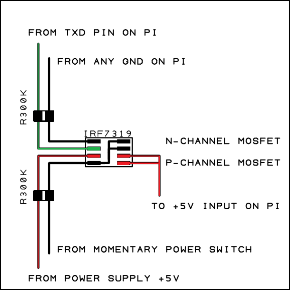
There are 8 pins on the mosfet, but the outputs have shared pins so there are only 6 connection points.
It’s a dual-mosfet (positive and negative) circuit. Pushing a momentary switch for a second or two turns the power on.
The circuit works like this:
The +5v wire runs from the power supply to the input on the P-channel mosfet, and the output from the mosfet connects to the Pi’s +5v input. Power is only supplied when the gate on the mosfet is connected to ground. This happens initially using the power button, one end of which is connected to ground. When it is pushed, the ground connects to the gate of the P-channel mosfet and power is supplied to the Pi.
The problem is that this will only keep the system powered as long as the button is held. This is where the upper half of the component, the N-channel mosfet, comes in. This mosfet works opposite of the P-channel, and has a negative input and output with a positive gate. Current only flows when the gate is positive. The positive gate of this mosfet is activated using the TXD pin on the Pi. This pin is typically used for serial data communication, but it has some characteristics that we will make use of here. It’s not the only pin that can be used, it just has a feature enabled by default.
The TXD pin switches to 3.3v within about a second of the Pi powering on. This means that the initial press of the power button connects the ground to the P-mosfet gate and turns the Pi on, and after about a second of holding the button the TXD switches to 3.3v. The TXD is connected to the gate of the N-mosfet, so when the TXD switches to 3.3v it turns the N-mosfet on. The output of the N-mosfet is connected to the gate of the P-mosfet, so it now serves as the ground connection for that gate and makes holding the power switch unnecessary.
The Pi is now powered on and is stable in that condition.
Now, let’s backtrack slightly. There are also resistors in this circuit. They serve the purpose of making sure the mosfets don’t switch on by accident. The resistor on the N-mosfet keeps the gate at ground under normal conditions, and when the gate is at ground the mosfet is turned off. The resistor on the P-mosfet keeps the gate at +5v under normal conditions, and when the gate is at +5v the mosfet is turned off. These resistors only do their job of pulling voltage down and up when the circuit is powered off, and they have no effect when the circuit is on. They are absolutely necessary. If they are not in place, the system will power on randomly.
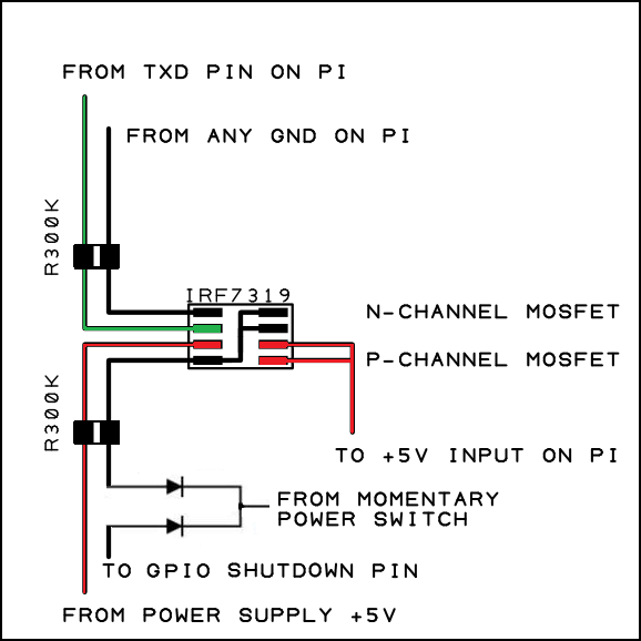
There is one more feature included in this circuit, and it’s the ability to fully power the system off when the operating system is shut down. The operation is simple. When the OS shuts down it switches the TXD pin back to ground. Since the TXD pin needs to be at 3.3v to power the gate of the N-mosfet (which in turn powers the gate of the P-mosfet), the whole circuit immediately shuts off. The resistors come into play here as well. If they were not in place, the system may not shut off immediately or may not shut off at all. They pull the gates down and up and kill power to everything. The Pi is now powered off and is draining zero power from the power supply or batteries. It can be powered back on immediately by holding the power button again.
Advanced Feature:
One additional great feature to have is the ability to shut the Pi off using a pushbutton switch. Even better than that is the ability to shut the system down using the same button that turns the system on. With a small addition, this circuit can be used for both the power-on and power-off. One diode is added between the momentary switch and the P-channel mosfet gate, and the other diode is added between the momentary switch and a GPIO pin. I recommend the BAT54C Dual Diode because of its small size. The GPIO pin will detect a press of the switch when the OS is running, and it will issue a shutdown command.
Questions? Comments? Leave a reply or visit the forum.
Hey,
I think this is a brilliant solution! I have googled around alot for a proper powerdown solution, but all I have found seem complicated. This is simple and so elegant with self powered pullup/downs.
Could you add the dual diode to this you think? I dont quite get from the main build page how this is hooked up and how it works. Is the momentary switch fpc slice soldered directly to the cathode of the diode, pulling down both the P-gate and the gpio?
Cheers!
That’s right. The anodes of the dual diode are connected to the p-mosfet gate and the gpio (and the gpio has to detect the voltage drop and issue the shutdown). The cathode connects to the momentary switch. I should probably add some more details and pictures showing that the diode should be included if youre doing a gpio shutdown. Also, I’m going to put a software guide together for the shutdown portion.
I’ve updated the guide to more clearly show the addition of the diodes.
That’s great very nice of you, thanks!!
Thanks for a very nice tutorial!! I was just wondering regarding the software part you wrote about (“The GPIO pin will detect a press of the switch when the OS is running, and it will issue a shutdown command. There is a major software component to this, and a guide is forthcoming.”)
Do you have any news on this guide? 🙂
best regards
André
All my focus has been on getting these boards made. I’ll get that guide up soon. The bulk of the guide is just the installation of RPI.gpio and then running a script at startup that looks for a voltage drop on a pin.
So scratch what I said earlier. Either RPi.GPIO wasn’t included in the earlier builds or it just wasn’t functioning on my install and had to be reinstalled. It’s included and functioning in the newest RetroPie. Anyway, that means it’s very easy to get the shutdown button working. I’ll have an updated guide showing the whole process soon.
Sweet! Thank you very much for all the info!
I haven’t forgotten about you. Still trying to make the time to write the shutdown code and post an update.
Hey, thank you for this great guide. I have one question, where does the power supply – go? To the switch, right?
I’m not sure exactly what you’re asking. The ground of the power supply connects to the switch.
Amazing guide, thanks for this.
One question tough: where exactly do the resistors habe to be placed?
For the P Channel, is it +5V or on the Switch?
And on the N channel on the GND or TXD?
If they have to placed on all the mentioned, how can you do it with just resistors?
(Sorry for the newb question ;))
It’s all of the above. One resistor connects to +5V and the Switch, the other resistor connects to GND and TXD.
Can post the python script for the shutdown om raspberry pi? Do we need a supercapacitor on the +5V input to PI connection? The reason is the raspberry pi needs some time to shutdown. Your advice? Thks
The on/off board doesn’t need a time delay or power buffer. It waits for the OS to shut down before turning off. I don’t have code I can post right now, but once I get some time to make it I’ll add it to the guide.
You need something like this:
http://www.instructables.com/id/Simple-Raspberry-Pi-Shutdown-Button/
If the Tx pin in raspberry pi also connect to a wifi module cause any problem?
I wouldn’t recommend it. I’d say it’s a good idea to use another GPIO pin if you’re using the TX for another function.
Can I use any raspberry pi GPIO pin in replace of the Tx pin? Will the GPIO pin momentarily in raspberry pin during boot up? But some won’t recommend it as in this forum link https://www.raspberrypi.org/forums/viewtopic.php?f=44&t=35321
Any other advice?
Thks
I’d love to use this in an NES — can this be modified to use a non-momentary switch such that when the switch is closed it stays on, and when the switch is open it safely shuts down?
It can, and it shouldn’t need much modification at all. Is your switch SPDT?
The switch inside of the NES is a normally-open SPST (it’s actually a physical toggle button)
Nevermind — it seems to “just work” with my setup, no change to the circuit needed. Thanks for your help.
Yes, it should. I just hadn’t had a chance to respond. It works because your switch is acting much like the momentary switch, and this circuit doesn’t care if you keep the switch engaged. If you want the OS to automatically shut down when you slide the switch to the off position, you’ll need software to pull a pin high look for it to go from low to high. Having the switch in the on position will keep the pin low.
Have been looking on the net for a way to build a on/off switch for raspberry and found that, seems simple to implement, thanks!!
Sure its a newbie question but…. I have a doubt about how to put the momentary switch , its connected to the diode cathode and to the ground power supply?
That’s right, switch goes between cathode and ground.
thanks!
I just tried to measure the TXT voltage and can confirm, that the TXT Pin will go to 3.3V right after the pi has been powered on. Unfortunately in my case the pin will go back to 1.2V just about a second later when the kernel is loaded.
Serial port has been enabled here but is now explicitely disabled using enable_uart=0.
However it shows up in dmesg:
root@raspberrypi:~# dmesg|grep -i ttyAMA0
[ 2.111682] 3f201000.uart: ttyAMA0 at MMIO 0x3f201000 (irq = 87, base_baud = 0) is a PL011 rev2
What am I doing wrong here?
I’m updating the guide for the improved power schematic, and I’ll be updating this one too once I’m done. Previous versions of the OS pulled the TX pin high and kept it there, but the new ones don’t appear to do that. I used that pin because it made the process easier for everyone.
Anyway, your solution is to add a line to config.txt
dtoverlay=gpio-poweroff,gpiopin=14,active_low=”y”
That will pull the TX pin high at bootup and low at shutdown. You can change the gpiopin=14 to use any other GPIO pin if the TX pin continues to be difficult.
Hm using this setup I will end up having Pin 14 at 3.3V and again Powered of for a short while then switching back to 3.3V when the Kernel starts to boot.
Thus I will end up having to hold the button until I bridge this off gap.
Any workaround?
How long do you have to hold the button?
It takes about 2 seconds till the first positive edge appears. High level is gone again after one second (or even less) and will re appear after another 2 seconds.
I think about using a monoflop to generate a power-on pulse of ~6 seconds.
That’s pretty typical for the GPIOs. Yea, anything that will hold the N-FET gate high or the P-FET gate low for a few seconds.
This is one reason I moved over to the newer power circuit.
OK, this works for me now adding a 74HC4538 based Monoflop instead of the Power switch which is now used as a trigger for the Monoflop.
How could i implement this to use it in a car. For example when the car is turned off it auto shutdowns the pi and cuts the power preventing the pi from draining the battery? I’ve tried looking at the improved emergency shutdown version but it seems to have been removed.
I moved everything to http://othermod.com/product/advanced-onoff-board/
It shouldn’t be too bad to adapt it for your needs. An accessory wire could be used to send a signal to a GPIO and issue a shutdown. Would just need something to shift 12v down to 3.3v.
Thanks for the smart design! Shall try it one day.
Just contribute a bit by showing a complete circuit. Hope it helps someone like me who are visual guy!
https://drive.google.com/open?id=1zWKuYCPKyBOJmbojBme7qymdjaH92fg5
I’m looking to integrate this circuit into a project I’m working on that uses Helder’s RetroPSU. Like the Adafruit powerboost, Helder’s board has an EN pin to toggle off the boost. Do you have any diagrams showing how to use this circuit with Helder’s or Adafruits power boards that toggle the EN? I did purchase a PCB from OSH park (https://oshpark.com/shared_projects/WP3Y5Keo) to make my life a little easier but judging from the second diagram, it look like this board just sends the power down signal to the shutdown pin on the pi but obviously won’t power down Helder’s PSU. I’m new to safe shutdown circuits so excuse any false assumptions on my part. Thanks for any help you can offer.
What exactly is the shutdown pin? One of those 2 pins below the RCA pins?
Pingback: Game Pi 3.5″ with Analog | 3d print ......errori ed esperienze,