


Description
The design files are open source, if you want to make your own:
https://github.com/othermod/DPI-Topper-666
If you want to support these open-source designs with a donation, you can do it here:
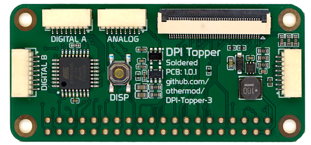
The board uses the DPI feature on the Raspberry Pi
https://www.raspberrypi.org/documentation/hardware/raspberrypi/dpi/README.md
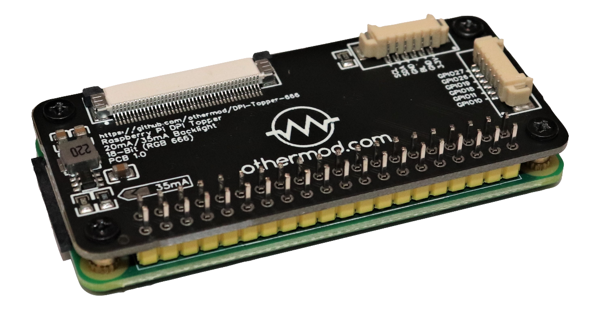
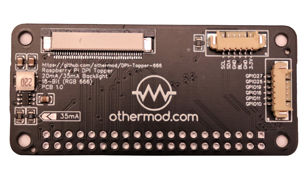
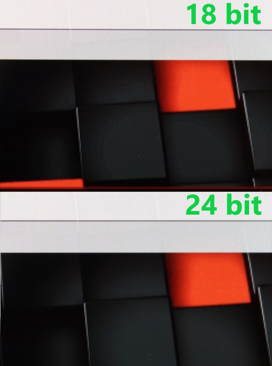
It drives an LCD using just the GPIO pins. It runs the display at 18-bit RGB666, which leaves multiple GPIO pins available for other uses. The board has a 6-pin 1.25mm JST connector with GPIOs 10, 11, 18, 19, 26, and 27 made available. This board also gives access to GPIOs 2 and 3 (the I2C pins) due to the way the LCD is configured.
This uses substantially less power than a composite or HDMI board, mostly because there is no IC converting the interface. Power consumption can be lowered even more if you take advantage of the BL pin to lower the brightness, which is controlled using a 2 kHz or lower PWM signal.
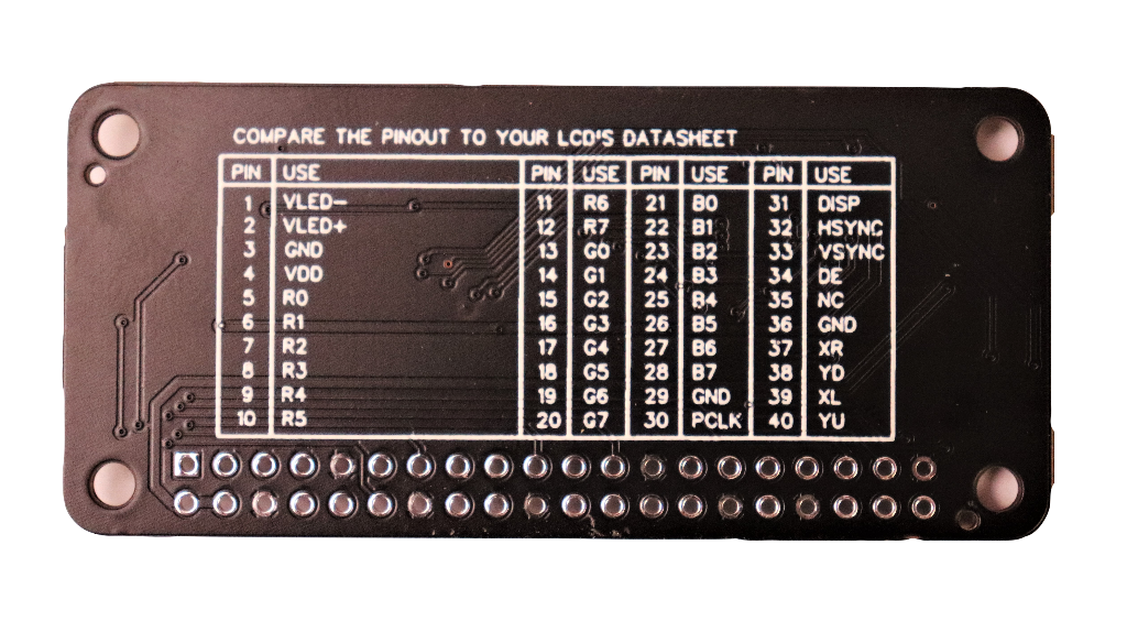
The topper is able to drive a 4.3″ to 7″ LCD as long as the pinout matches and you can decipher the timings from the datasheet. Most LCDs use the same timings. The backlight power is set using resistors on the board, and it’s pre-set to 20mA. This is the optimal amperage for many 4.3″ LCDs. There is a pad on the board that will add another 15mA (so 35mA total) when bridged.
I have personally tested the following 800×480 LCDs with the new Topper:
- https://ebay.to/3aDlQ61
- 4.3″ LCD. Part number ER-TFT043A1-7
- This is the best quality 4.3″ LCD I’ve ever used.
- http://s.click.aliexpress.com/e/rf6yNvR
- 5.0″ LCD. Part number KD50G21-40NT-A1
- Great image. This is the same LCD Adafruit sells here
- https://ebay.to/2kxCGdu
- 7.0″ LCD. Part number ER-TFT070A2-4
- Very expensive. I’ll list cheaper alternatives soon.
I have a stack of various LCDs, and I’ll add more model numbers as I test them (both 480×272 and 800×480 resolution ones). So far, every LCD I’ve tested has worked perfectly in the new Topper.


Reviews
There are no reviews yet.